

By John Anello, Auto Tech On Wheels
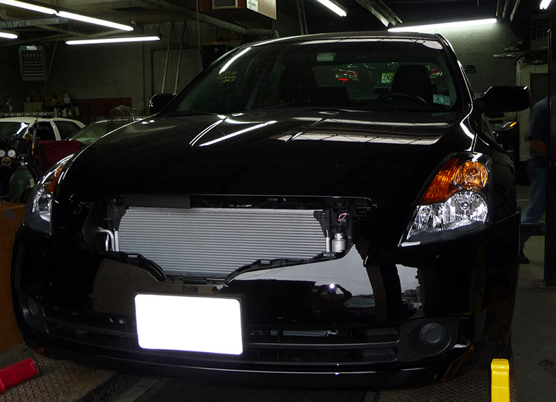
I was called to a shop with a complaint of no A/C compressor engagement on a 2008 Nissan Altima with a 2.5L engine (Figure 1). The vehicle was recently involved in a front-end collision and the PCM and engine harness were both replaced. The technician had checked all fuses and rechecked the harness connections, but could not resolve his diagnostic dilemma. The inside A/C panel responded to selections and the LED on the panel illuminated when the A/C mode was selected. The system was properly charged with and there were no service codes present in the PCM when a scan tool was connected. At this point, the shop decided to call me in for a second opinion.
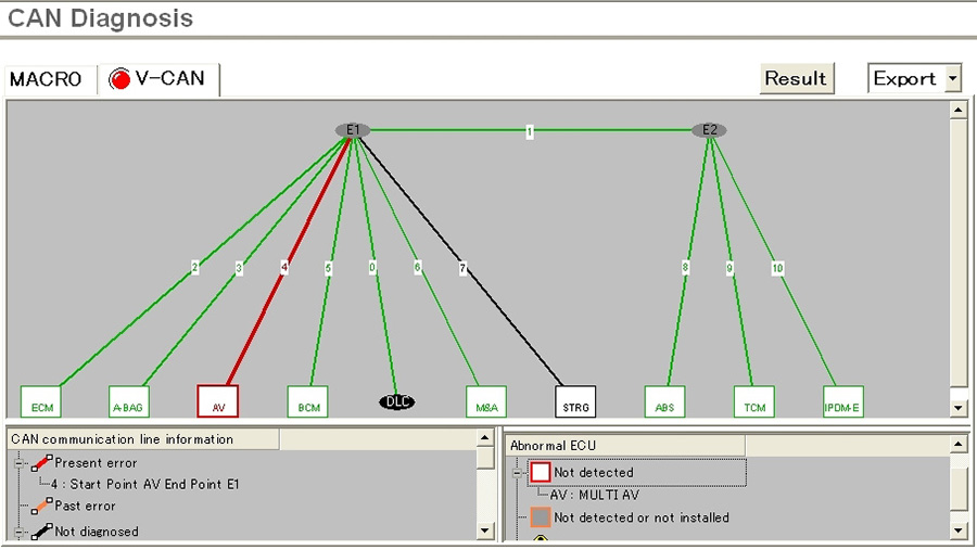
Topology Network View
When I arrived, I hooked up my Nissan Consult III to the vehicle to confirm the shop’s findings. I selected the topology network view (Figure 2) to see all the controllers on the network at the same time and to see if there were any codes stored in any of the operating systems. Network view is a feature that many factory scan tools are beginning to support. Not all manufactures are doing it, but the industry is slowly moving in this direction. It provides a technician with a quick visual mapping of the entire vehicle by the use of colored icons representing each control module. These modules will be different colors depending on if they have current, history, or no codes stored in memory. The lines drawn among the controllers may also use color coding to represent different types of networks, or even networks that no longer respond. This type of layout allows the technician to build quick associations with controllers when problems arise within the network. By simply looking at the network, I could see that there were no trouble codes within the PCM or any of the other controllers. The Audio Video controller was not responding on the network because it was an option that was not present, as the red line drawn to it indicates.

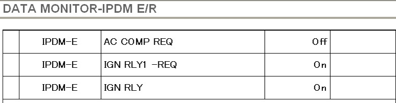
I did not know the system strategies of how the A/C compressor was controlled on this vehicle once the A/C button was pressed. The command was sent out into the network, but the request path was something I needed to find out. I first printed a diagram of the A/C system (Figure 3) and I was surprised to see that the Integrated Power Distribution Module (IPDM) was in charge of controlling A/C relay operation, but it was not grounding the relay when the A/C-on command was sent from the A/C panel. I used the scan tool to navigate to IPDM data (Figure 4) and could see that the IPDM was not receiving a request to activate the A/C relay. This request was being suspended somewhere in the network between the A/C panel and the IPDM, but the question was where. It was a request that had to travel through the CAN network, which the IPDM was tied to. I just had to dig a little deeper to find out which controller or controllers were responsible for giving the final command.
BCM & IPDM
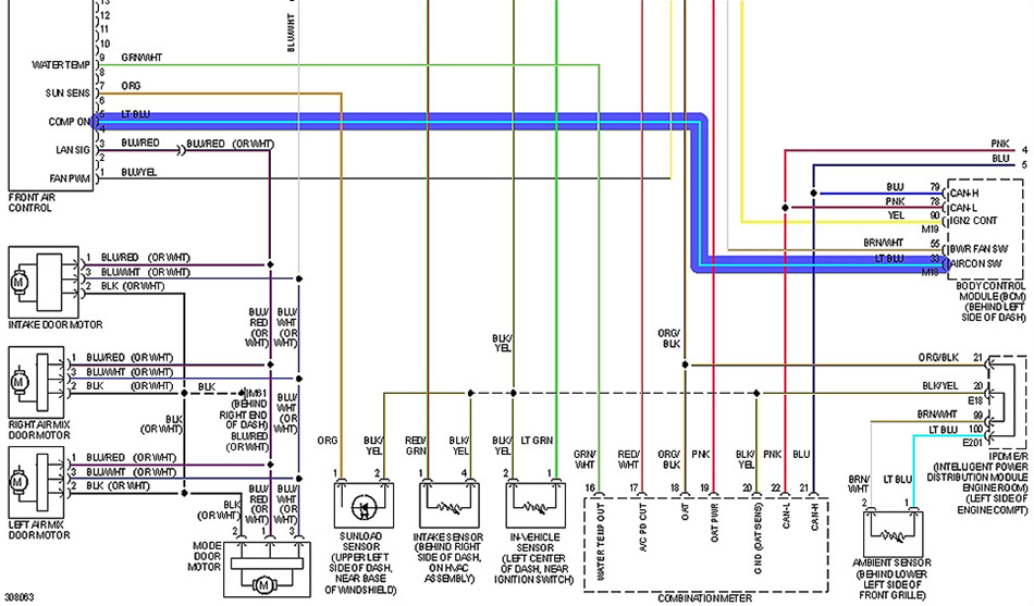
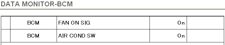
I next printed out a diagram of the A/C control panel to see where the command signal was being sent (Figure 5). By looking at the diagram, I could see that the request was sent directly to the Body Control Module by a command signal line from the A/C control panel. I used the Consult III to navigate to BCM data (Figure 6) so I could validate that the BCM did indeed see the request from the A/C panel. The BCM definitely was receiving the A/C-on command, but there had to be another controller that had higher authority in controlling the A/C command output because the BCM did not pass this command on to the IPDM controller. The only computer on the CAN network that would have more authority over the BCM for the A/C command would have to be the PCM. Engine control modules have always been in control of A/C relays in the past because they had to look at more criteria than most controllers on the network prior to making a final decision on A/C clutch activation.

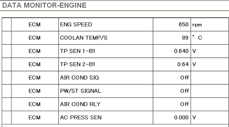
Color Confusion

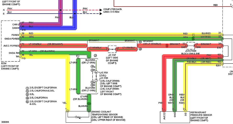
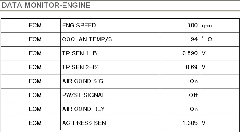
Engine controllers will usually take into consideration data PIDs such as coolant temp, throttle position, power steering pressure, or possible A/C input sensing devices. I had to print out a diagram of the Powertrain Control Module to see how it played a role in the activation of the A/C clutch (Figure 7). By closely looking at the diagram, I could see that the A/C pressure sensor was directly tied to the PCM to monitor the operating range of the pressure within the A/C system, so I decided to use the Consult III to navigate to the PCM data stream and pull up some PIDs of interest (Figure 8). It is important to fully understand the operating ranges of sensors because there may be situations where a sensor value is still within range, yet causes a system-related problem without ever setting a code. The sensor values I selected were rpm, Coolant Sensor, Throttle Position Sensor 1, Throttle Position Sensor 2, A/C Signal out, Power Steering Switch signal, A/C Relay Command, and A/C Pressure Sensor. After viewing the data, I noticed that the A/C pressure was at 0 volts indicating low refrigerant pressure in the system. The PCM never set a code, but decided to keep the A/C clutch off due to the low-pressure condition. The system was properly charged, so there had to be an issue with the A/C pressure sensor or its wiring.
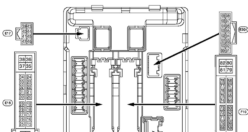
I located the A/C pressure sensor at the left front of the engine compartment (Figure 9) and tested the wires for proper ref voltage and ground feed. Keep in mind that a low signal output is always an indication of a shorted or open signal line to the PCM, or an open or shorted ref voltage line to the A/C pressure sensor. What I discovered was that there was no reference voltage on the pink wire at the A/C pressure switch, and the circuit was not shorted. I now had to find my way back to the Integrated Power Distribution Module to check the circuits going in and out of it. The information system I was using could not provide me with a connector view of the IPDM, so I had to resort to another information system (Figure 10). Looking at the connector view, I now knew where the pins were located in the IPDM, but I also had conflicting information with the diagram colors from the first information system I had been using. Checking the Pink 5 volt ref at pin #103 showed no ref voltage, but the 5 volt ref into the IPDM from the PCM was not Brown and White at pin location #24, but rather Green (Figure 11).

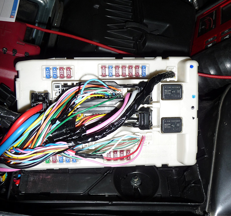
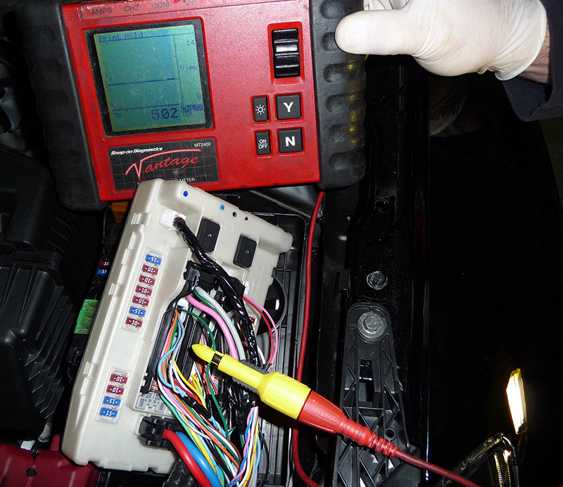
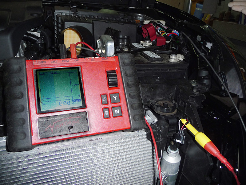
The wiring diagram information was correct on pin location, but wrong on color identification. This is something that can happen with any information system, so you need to be very alert and even have another information system available to compare notes with. If you look closely at the wiring at the upper right side of the IPDM, you can see that the Red and White wires were twisted together to use the White ref ground wire to cancel any noise on the Red signal line. On the left center of the IPDM, the Gray and Blue wires were twisted together using the Blue ref ground to cancel noise on the Gray signal line. When I checked the Green ref voltage line (Figure 12), I discovered that the PCM was sending the 5 volt ref to the IPDM, but the ref voltage was not coming out of the IPDM on the pink wire. The IPDM had an internal board problem. I then went one step further and started to flex the module. I heard the A/C clutch engage! So, I monitored the PCM data and flexed the IPDM again, and I captured a screen shot (Figure 13). You can see that the pressure switch was reading the proper output of about 1.3 volts.
When this car was involved in the collision, the IPDM most likely got damaged from the impact. There was no visible damage to the unit, but the shock was enough to create an internal open circuit in the A/C pressure sensor circuit. There were no codes in the network to point me to any areas of concern. The only thing that allowed me to find the problem was knowing how the system worked and how to read scan data. It is also important for the technician to be aware that his information is not correct, which will keep him from going down the wrong path.


I’ve just solved a problem of CAN in a Kia Sedona 2007. Your article about diagnosting networks helps me.
It’s very interesting. I recomend it.
Thanks