
The players and the product
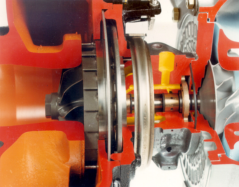
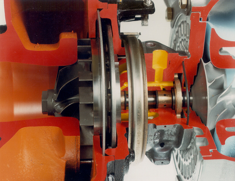
Numerous companies manufacture turbochargers: Garrett, Banks, Borg-Warner, Cummins, Toyota, Rotomaster, Holset, IHI-Warner-Ishi, Rayjay, Schwitzer, Komatsu, and Mitsubishi, to name a few. The basic automotive and light truck turbocharger consists of an axial inflow, radial outflow compressor on the intake side coupled on a common shaft with a radial inflow, axial outflow turbine on the exhaust side. “Radial” and “axial” refer to the direction of gas movement. Punch the point of a pencil through the center of a cardboard circle. Radial flow would originate at the rim of the cardboard circle and move inward to the pencil where it penetrates the cardboard circle. Axial flow would originate where the pencil enters the cardboard and would move along the length of the pencil to the eraser end.
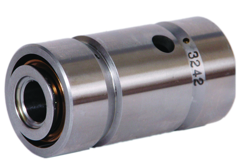
The heat and pressure of the exhaust side is harnessed in the turbine, which drives the compressor through the common shaft. The shaft may be supported by a pair of floating bronze journal bearings and a separate thrust system, or by the newer ball bearing system with integral thrust control, and there are good reasons why the former gave away to the latter. Ball bearing center housing rotating assemblies don’t need a separate thrust control system since the shouldered thrust faces of the two ball bearings are installed opposing each other, thus controlling thrust in both directions. Plus, ball bearings are more tolerant of lubrication shortcomings, and also spool up more quickly, dramatically reducing the dreaded turbo lag. If you were looking for a word to describe turbochargers, that word would be “precise.” The turbine and compressor wheels are carefully positioned in their respective housings with .010-.020 in. of clearance to the contour bores. The precision-machined housings change in volume from inlet to outlet to maximize energy extraction on the turbine side and air movement on the compressor side. The size, shape and contour of the volutes (the spiral, scroll-shaped form of the housing that resembles a ram’s horn) are critical to turbocharger flow rates and efficiency.
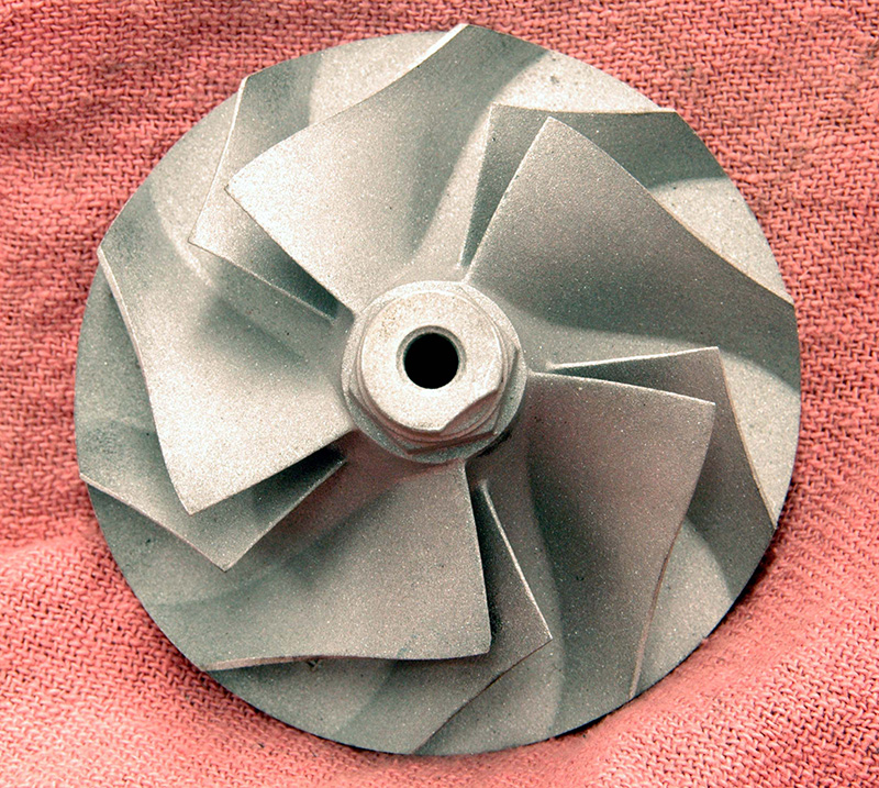
By convention, the inlet of a turbine or compressor section is called the inducer section and the outlet the exducer section. A ratio of the relative sizes of the inducer and exducer sections is often expressed as a trim number, helpful in sizing the turbo correctly. Since space limitations restrict the use of a more efficient axial-only turbocharger, blade shapes on the turbine and compressor wheels are engineered to reduce the losses generated as gases make the 90 degree turn through the housing. Turbine blade shape constricts at the exducer to extract maximum power from gases that are gradually slowing and cooling. Viewed on end, a turbine blade suspiciously resembles an airfoil — there’s a lot going on here! Inlet pressure on the turbine (hot) side is generally within a few pounds of the actual boost, about 15-20 psi, which translates into a pressure drop of about 13-18 psi across the turbine wheel at full load if the exhaust system backpressure is two pounds. Expect full load temperatures to drop about 300 deg. F. from a 1,200-1,500 deg. inlet reading. It’s that temperature and pressure drop across the turbine wheel that provides the energy necessary to spin the compressor.
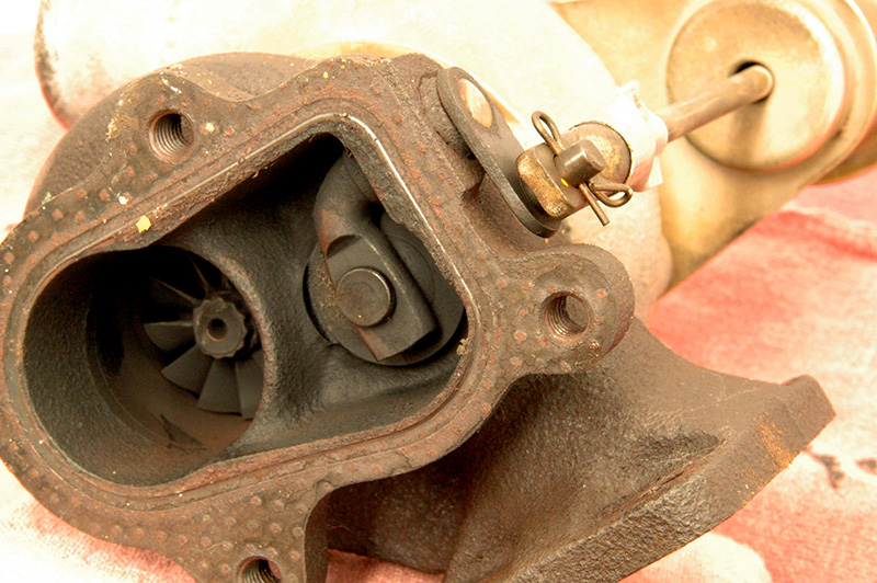
On the compressor side, the amount of boost is controlled by a wastegate, or by a variable nozzle arrangement on the turbine side. The wastegate is a simple bypass system. Inlet pressure is routed over to a spring-loaded diaphragm that opens a passage to bleed exhaust gas around the turbine. Less flow and heat through the wheel means slower turbine speed, hence slower compressor speed and less inlet pressure. Simple and elegant. The VNT system eliminates the wastegate. Vanes mounted on pins and connected by linkage are actuated together to limit exhaust flow or change gas direction through the inducer of the turbine wheel, slowing the rate of rotation and reducing boost.
Overdone
There are limits to per-liter internal combustion power output, no matter how exotic the materials and build techniques. With turbocharging (or supercharging, for that matter), you risk changing the timing of the intake valve closing event, taking the engine to detonation, or finding the mechanical limits of the head gasket, block, fasteners, or cylinder head. There’s a great picture on the Internet of a tractor puller who yanked the block of his six-cylinder engine in two just where the head studs stopped in the block when his boost gauge hit 300 psi! Let’s see, 300 psi times 16:1 is . . . a helluva lot of pounds of force!
Potential intake valve closure issues are really only a problem in all-out performance applications unless there’s a failure that creates unregulated boost. In high-performance applications, valve closure issues are overcome by design: limit the boost, increase valve spring pressure, keep intake valve diameter down, grind the cam for boost application, or modify the rpm band. Assuming cylinder pressure is zero, a two-inch valve with 15 psi intake boost only has about 50 pounds of force counteracting the valve spring. But our pulling tractor at 300 psi? Assuming it’s a four-cycle engine, that same two inch valve would need almost 1,040 pounds of spring pressure just to overcome inlet pressure.

YOU SEEM TO HAVE FORGOT SAAB’S TURBO CARS