
The three legs of the tripod that supports internal combustion in an Otto Cycle engine are compression, fuel supply/injection, and ignition. The job of the ignition system is to provide the spark that initiates combustion, and it’s our job to keep this process going. To do that effectively, we need a firm grasp of how the system works.
Many of us hold a basic misconception about the gasoline-burning internal combustion engine: We think that the ignition spark is the instigator that ignites the mixture. Period. While this is true, it is not always true. As we’ve learned from the engine Rudolph Diesel designed, if we compress an air/fuel mixture enough, the charge will ignite on its own – ergo, the diesel engine. Diesels do need some help to get started in cold conditions, such as glow plugs that heat the combustion chamber before and during cranking, and block heaters that keep the engine relatively warm, but once started it generates its own heat and combustion pressure keeps the process going.
Almost, but not quite
The Otto cycle internal combustion engine also compresses the air/fuel mixture to a point where it is about to ignite, but not compressed so much it ignites on its own. If it does ignite on its own, we have something called pre-ignition.
The Otto cycle internal combustion engine operates by compressing the air/fuel mixture to the point where it is about to ignite, and then a spark is created at a precisely-timed moment to start the ignition process. This process typically begins a few degrees before the piston has reached top dead center (TDC), which is known as ignition advance.
Advance is why an Otto cycle engine typically makes more horsepower that its diesel counterpart with similar displacement. A diesel brings the air/fuel mixture to compression ratios of 16 to 1 or higher, but ignition only happens at peak compression with the piston at TDC. The piston is now beginning to travel downward as the combustion process starts and the expanding gases force it down. This allows diesels to make exceptional amounts of torque, but relatively low horsepower.
Suspicions
But what if you don’t have ignition in a gasoline engine? Could the problem be coil-related? Ignition system diagnosis is in order, assuming you have made sure spark plug and coil wiring is properly connected – the system must have primary circuit current to produce the magnetic field that, when it collapses, induces the high voltage needed to fire the spark plugs.
The gasoline-burning Otto cycle engine begins the ignition process with the spark across the plug electrodes. At low rpm, this begins a few degrees before the piston has reached TDC. This is due to a short lag called flame front travel. When the spark occurs, the entire combustion chamber is not immediately filled with burning gases — it takes milliseconds of time for the fire to spread all the way to the cylinder walls, and by that time the piston is starting to move downward.
If the mixture ignites too early (as we said, pre-ignition) the gases will push down on the piston before it has reached TDC, slow it down and reducing horsepower. If the mixture is ignited too late, the piston will have passed TDC and the combustion gases will push down on a piston that is already traveling downward, and complete combustion may not take place, also reducing horsepower. The spark has to happen at just the right time for efficiency.
Ahead of time
As engine rpm increases, there is less time to burn the mixture, and the timing must be advanced to start the ignition process earlier. In old-fashioned ignition systems, centrifugal weights and springs, and vacuum units were used to advance the spark as engine speed increased. A modern Powertrain Control Module (PCM) uses crankshaft and camshaft position sensors to detect where the piston is in its cycle, and takes other inputs into consideration while deciding when to start the ignition process.
This gives modern engine management systems complete control of when the spark occurs, and the PCM can immediately react to changes such as engine knock, load, and temperature. When a knock sensor tells the engine management system that detonation is occurring, which is damaging to the engine, the PCM retards the timing until the knocking stops. Other factors such as engine load signaled by the manifold absolute pressure (MAP) and mass air-flow (MAF) sensors, engine coolant temperature, and charge air temperature affect how the PCM regulates ignition timing.
While the voltage that rises quickly at the spark plug electrodes is obviously important in forming the spark, another key to efficient ignition is the amperage present, the actual energy of the spark. There’s nothing a technician can do, however, to alter what the electronics make available to produce what’s called the flame kernel.
Triggering
The basic test of an old-fashioned ignition coil was simply to measure the resistance of the primary and secondary windings. But no more. Systems today are far more sophisticated and promote far greater engine efficiency — and require more sophisticated testing.
Volkswagen electronic control units regulate the ignition coil ground in one of several ways. The PCM can ground the coil directly with an internal driver, or it can send a trigger signal to a transistor built into the coil. When engine management systems first began controlling the ignition system, they would often send these trigger signals to separate ignition modules that handled the heavy-lifting of grounding the coils, thus generating the spark. Most of today’s ignition systems, however, use a coil over plug (COP) design, which means there is coil for each spark plug, and an ignition module for each coil, at the spark plug, each controlled independently. This allows the engine management computer to regulate ignition timing for each cylinder individually, and can help reduce misfires that are isolated to a single cylinder. This makes diagnosis a little more difficult since we now must test a separate ignition system for each cylinder.
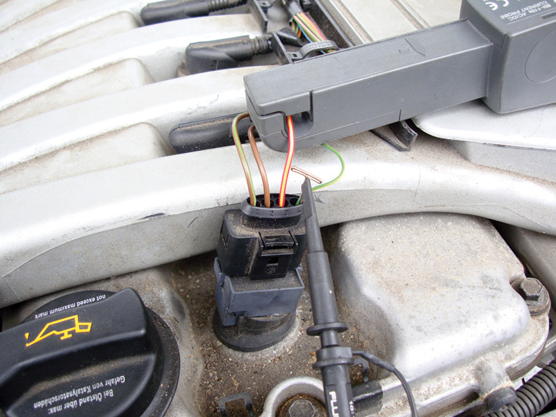
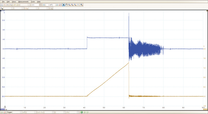
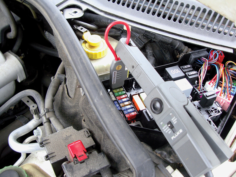
With the ignition module built into the coil assembly at each plug, we can no longer check the resistance of the primary windings, but we can still check the resistance of the secondary windings. However, there are other ways to check an ignition system rather than a resistance test of the two ignition coil windings. We can monitor the voltage of the primary and secondary windings by induction — by measuring the voltage on the coil power supply wire we can see its fluctuations as is passes through the primary windings.
With the proper adapters, we can also monitor the voltage pattern on a lab scope by resting an inductive probe on the coil. We can also use an inductive low-amp probe to monitor the amperage draw of each coil, and we can compare the pattern of a good coil with that of a malfunctioning one.
COP
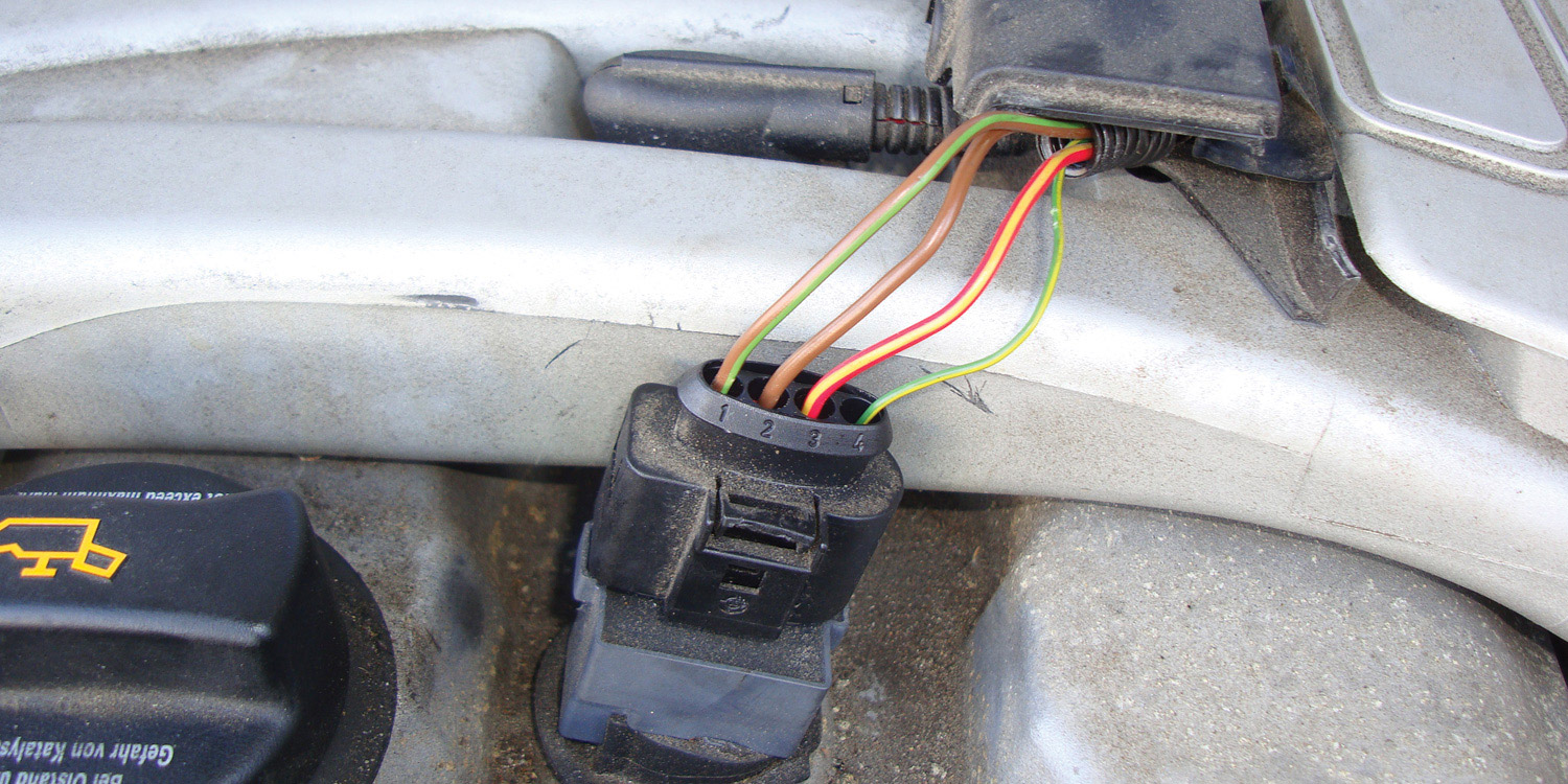
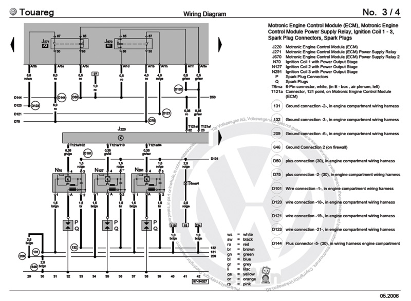
We’ll use a 2006 Volkswagen Touareg ignition coil as our example of a modern unit with the power transistor incorporated into it. It is a four-wire coil. Pin #1 is the ground for the power transistor inside the coil and grounds on the firewall of the vehicle. Pin #2 is the ground for the secondary winding of the coil.
To compare it to something you may be more familiar with, picture a waste-spark coil winding. That is, one coil with two towers, and the spark is pulled from one spark plug through the coil winding to the second spark plug connected to the same coil. If you ground one of the coils, the other coil will still fire when the coil is energized. That is the way this Volkswagen coil is wound. One side of the coil goes to ground, and the other side goes to the spark plug. However, you cannot use measurement of secondary winding resistance as a viable test.
This coil grounds to the actual engine block. If you fail to have spark after engine work, check these grounds.
The third wire, Pin #3, is the power supply for the coil. It comes from fuse S7 for cylinders #1 through #3, and S8 for cylinders #4 through #6 on the 2006 Touareg with the six cylinder engine. This fuse also powers the fuel injectors. You can use it to monitor the amperage draw of each coil while the car is running, and you will see the amp draw of each injector as well.
The final wire on the coil, Pin #4, is the trigger wire from the Motronic electronic control unit. The computer uses cam, crank, and load sensors to determine engine rpm and load, and then triggers the coil with the proper ignition advance to produce the most power with the best fuel economy. Knock sensors can pick up knock, isolate it to a cylinder, and retard the timing on that cylinder only.
Testing coils
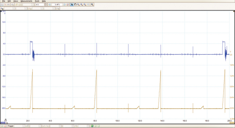
You can monitor the knock retard in one of the value data blocks using your VAG 5052, and with a dual-trace oscilloscope also see if you have a problem coil (a misfire?) by looking at the amp draw pattern for each coil. Use the second pattern to form a trigger so you know which cylinder is firing at the time, and you can follow the firing order from there. You can also scope the amp draw from fuse S7 or S8 to watch the amperage patterns for cylinders #1 through #3, or cylinders #4 through #6.
You will still see one trigger of the coil you select, and also see two additional amperage patterns for the other two cylinders. Keep in mind the injectors are being fired on this circuit as well. Compare the amperage patterns to see if any do not match, and chances are those are problem coils.
Knowing how a system should work before testing leads to a more accurate diagnosis that you can stand behind. Using Volkswagen parts will give you (and your customers) confidence that the repair is going to last, and we call that a win-win situation.


0 Comments