

When a customer comes to your shop with a possible charging system problem, the inspection should involve more than just checking the voltage across the battery terminals with the engine running.
Let’s cover the information you’ll need to avoid being bit by an incorrect diagnosis from a review of the charging system basics that have been the same since you started repairing cars, to some of the newer and perhaps unfamiliar control systems that have been added to fine tune the charging system for optimum efficiency.
The Battery
The battery has several functions. It powers electronic systems when the engine is off; it provides the power needed to start the engine; it can act as a ballast to stabilize voltage during periods of high electrical demand; and it provides backup power in the event of a charging system failure. The battery needs the charging system and the charging system needs the battery, so verifying that the battery is charged and in good condition is an important first step when testing the charging system.
One of the most common symptoms of a charging system failure is a discharged battery. More often than not, when a car arrives in your shop with a charging system problem, the battery will be discharged. The first step should always be to charge and test the battery. The best way to do this is with the GR8 Diagnostic Fast Charger, available from Nissan’s Tech-Mate tool and equipment program. Time is money and the GR8 is a time saver. The GR8 will quickly test the battery before fully charging to make sure you aren’t wasting time. It also uses proprietary pulse-charging algorithms to charge the battery faster than a conventional charger could while reducing battery sulfation at the same time. After the battery is charged to around 70%, the GR8 will alert you so you can begin charging system testing instead of waiting for the top-off mode to complete.
Charging Voltage
A 12V automotive battery is made up of six 2.1V cells connected in series for a total nominal voltage of 12.6V. The ideal charging voltage per cell is between 2.3V and 2.45V, so the charging system output should ideally be between 13.8V and 14.7V. At the lower end of the range, the battery will not reach full charge and the negative plates can become sulfated resulting in a reduction of battery capacity over time. At the higher end of the range the battery will get a full charge and maintain its capacity, but the positive plate may erode and the electrolyte may gasify, causing damage and loss of electrolyte.
What is the perfect charging voltage? The answer depends on a number of factors: the battery’s state of charge, the battery’s temperature, the condition of the battery, and the design of the battery. Most older Nissan cars simply kept the charging voltage fixed anywhere between 14.1V and 14.7V. Newer Nissan vehicles use information from temperature sensors and current sensors to modulate alternator output by using a control unit. This allows for increased fuel economy as well as optimized battery capacity and life. We’ll discuss how this happens and how you can diagnose the variable voltage controlled charging systems later in this article.
Alternator Overview
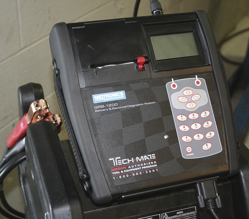
The GR8 Diagnostic Fast Charger is available from Tech-Mate.
The alternator consists of a variable-strength electro-magnet rotor, a regulator, a 3-phase stator and a rectifier. The rotor is linked to the crankshaft through pulleys and a drive belt, so when the crankshaft is spinning, the rotor speed varies proportionally to the crankshaft speed. The rotor’s moving magnetic field passes through the windings in the stator causing it to generate AC voltage. The faster the rotor spins, the more voltage the stator will generate. A voltage regulator controls the current through the rotor, which in turn, controls the magnetic field generated by the rotor. The greater the strength of the magnetic field, the more voltage the stator will generate. To increase charging voltage, the regulator increases voltage to the rotor and vice versa. The regulator has internal logic to control alternator output, but can also receive input from other control units to maximize fuel efficiency. Finally, the AC voltage generated by the stator is transformed to DC voltage by a full-bridge rectifier built with 6 diodes.
The Stator, Rectifier and Ripple

The EXP-800 can be used to quickly test many aspects of charging system performance.
AC current cannot be used to charge a battery because, even though the positive peak of the AC sine wave would push current into the battery, the negative peak would pull the same amount of current back out. Therefore, an alternator must convert the AC current into DC current that can be stored by the battery.
A rectifier is an arrangement of diodes that converts the AC current to DC current which can be used to charge the battery and power the vehicle’s electrical systems. A diode is an electrical check valve that only allows current to flow in one direction. An arrangement of 6 diodes allows the positive half of the sine wave to pass and inverts (flips) the negative portion of the sine wave so it too is positive. This results in a nearly complete DC output since there is a positive peak every 60 degrees. The alternator’s rectified DC output is further smoothed with a capacitor, which stores and releases current to eliminate the remaining ripple.
As technicians, why do we care about how the alternator creates DC output? We don’t need to build an alternator, we just need to find out if it’s working, right? The answer is that knowing how the alternator works will help us diagnose failures. By checking for ripple – the peaks of the AC sine waves remaining after rectification – we have a window into the function of an alternator. If a phase has a turn-to-turn short, reducing its inductance and output, it will show up in the ripple. If a rectifier or capacitor has failed, it will show up in the ripple.
Ripple can be checked in a number of ways. If your DVOM is fairly fast, you can check charging voltage using the AC scale. The ripple will be displayed as AC voltage while the DC output will not be measured. An oscilloscope can also be used to check ripple, with the added benefit of being able to see the pattern of the ripple. There is a peak every 60° and there are 360° in a rotation, so you’ll be able to see any faults repeat every six peaks. Test for ripple voltage at low engine RPM and low electrical load. Testing at high RPM or high electrical load with the 0.5V max recommendation could lead to falsely classifying a good alternator as bad. If in doubt over a ripple voltage reading, compare the value to a known good vehicle under the same engine RPM, electrical load and battery state of charge conditions.
The quickest and easiest way to test for ripple is to use the Nissan-approved EXP-800 Battery and Electrical System Analyzer (also available from Tech-Mate) or the GR8. Both tools are capable of testing for ripple and making a good/bad determination. Once again, using the right tool saves a lot of time and decreases the chances of making an error when interpreting the test results.

The alternator is commanded by the ECM on many modern Nissan vehicles. Make sure the alternator isn’t just “following orders” before condemning a unit with seemingly low output.
Rotor, Brushes, & Voltage Regulator
The stator and rectifier are not the only way the alternator can fail. The rotor, brushes, and voltage regulator can also break. The rotor is an electromagnet, so it must be powered to work. Because the rotor spins, the power must be delivered to it through spring-loaded carbon brushes that push against two commutator rings wired to either end of the winding in the rotor. An output of 13.8V-14.7V is maintained by regulating the current to the rotor. More current means a stronger magnet and a more alternator output. Less current means a weaker magnet and less alternator output. The voltage regulator is responsible for controlling the voltage to the rotor to control the alternator output. The brushes, commutator rings, rotor winding and voltage regulator can all fail, typically producing the same symptom – no charging.
Brushes
The brushes are made of carbon and are pushed against spinning copper rings, so the brushes will wear away with use. As the brushes wear and become shorter, the springs pressing against the brushes will extend. When the springs become longer, they press on the brushes with less pressure, increasing the possibility of poor electrical contact. Also, the brushes are typically rectangle-shaped when new, but will eventually wear into a square shape. When the brushes wear beyond a square shape, they can get cocked in the brush holder and stick, preventing contact with the slip rings.
Some technicians will tap on an alternator to dislodge stuck brushes while monitoring the charging voltage as a quick test. If the charging voltage jumps to “normal” at the exact same time the alternator is tapped, it’s a pretty good bet the alternator is bad. This test does frequently work. However, overzealous or poorly aimed “tapping” can result in a damaged alternator, which is especially bad if the alternator wasn’t the problem to begin with. It can also result in an avoidable core chargeback. You may have noticed that Genuine Nissan remanufactured alternators do not come with hammer marks on them. Unless you’re stuck on the side of the road, it’s best to use standard diagnostic techniques.
Regulator
 Earlier in the article we said Nissan is using current and temperature sensors to decrease fuel consumption and optimize battery life. The voltage regulator does not monitor these sensors directly. A control unit with more processing power monitors these sensors and makes decisions, then relays a command to the regulator.
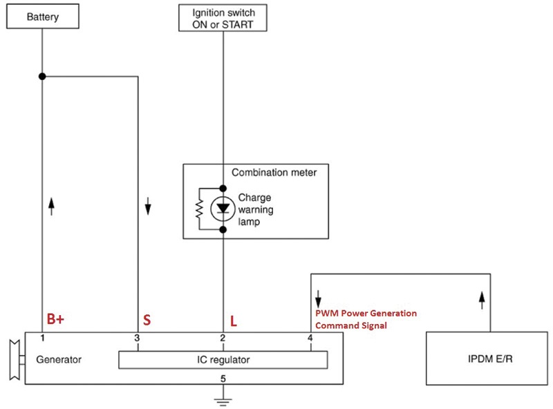
For instance, the ECM may monitor the sensors, send a charging command via the CAN bus to the IPDM E/R (Intelligent Power Distribution Module Engine/Room, usually part of an engine room fuse box), the IPDM E/R then issues the command to the voltage regulator with a PWM (Pulse Width Modulated) signal. In the event that the IPDM E/R signal is not received by the voltage regulator, it charges the battery based on its own logic, without the benefit of the information provided by the additional sensors.
Why is knowing this important? Well, if alternator output is lower than expected, we need to know if this is because that’s what the ECM is trying to do, or if there is an alternator fault. So, before doing any further testing, we need to disable what Nissan calls the “Power Generation Variable Voltage System.” The easiest way to do this is with the CONSULT III plus using “alternator duty%” active test. When the duty cycle is either 0% or 100%, the voltage regulator will run the alternator, based on its own logic, just like on older cars. This will allow you to perform alternator testing without the ECM interfering.
If you don’t have a CONSULT III plus, you should probably get one because it makes fixing Nissan products a lot easier. In the meantime, you may be able to disable the ECM control by disconnecting the current sensor depending on the car. Check the service manual and then verify the system has been disabled by checking duty cycle at the voltage regulator Pin 4. A steady state voltage, either ground or B+ means the voltage regulator is in control and the ECM isn’t affecting the charging voltage.

This car has very little voltage drop on the B+ cable while idling with no loads, but it should be tested with several loads turned on before declaring the positive side of the circuit “good.”
As implied by the fact there is a Pin 4, there are 3 other alternator terminals, and they are also important to diagnosis. Let’s cover these now.
The B+ terminal is the alternator output. If charging voltage is low at the battery, it’s important to make sure that it’s also low at the alternator, and not being “eaten up” by voltage drops on the way to the battery. You could measure voltage across the battery terminals and then from the B+ terminal to the alternator case and compare them. They should, of course, be very nearly equal. However, a better way is to connect one lead to the positive battery terminal and the other the B+ terminal. Any voltage displayed on the meter is being “eaten” by the cable and connections. The same test should be performed between the alternator case and the negative battery terminal. By checking for voltage drops this way, you’ll know which side of the circuit is in trouble and you’ll also be testing both locations at the exact same time, so you’ll know the current flow was the same during the testing. Which brings us to another important fact about voltage-drop testing: the amount of voltage drop on a circuit is proportional to the current flowing through the circuit. If you want to really test for drops, make the alternator work hard by activating electrical loads like the headlights, blower, seat heaters, etc.

When checking voltage at the terminals of the alternator everything should be plugged in and the car should be running. Carefully sliding a T-pin between the weather packing and the wire provides a way to check voltage on a live circuit without disconnecting or causing damage.
Another terminal is the “S” terminal, or sense terminal. This terminal is how the voltage regulator knows the charging voltage so it can make adjustments. This information is pretty important for charging system operation. You may wonder why the voltage regulator doesn’t just tee into the B+ terminal internally. The B+ wire goes right from the alternator to the battery right? Here’s why: remember the voltage drops we were checking a paragraph ago? The S terminal wire does tee into the B+ wire, but it does so closer to the battery so the system will be more tolerant of voltage drops on the B+ wire. This will allow for more accurate voltage regulation at the battery, where it matters.
Finally, there’s the “L” terminal. L is for “lamp,” as in the charging system warning lamp. When the alternator isn’t charging, the L terminal is grounded through the voltage regulator. When the alternator is charging, the L terminal has battery power. The charge warning lamp in the combination meter is connected to key-on power and the other side is connected to the L terminal. So, when the key is in the ON position and the engine isn’t running, the warning lamp should illuminate. After the engine is started and the alternator starts charging, the lamp should go off. A bulb check is an important, and very easy, test when performing charging system diagnosis.
In closing, keep these rules in mind for your next Nissan charging system challenge:
- Make sure the battery is charged and in good condition before testing the rest of the charging system.
- Use the CONSULT III plus or other methods to disable the Power Generation Variable Voltage System before testing the alternator output.
- Check voltages at all 4 alternator terminals whenever alternator output is low, high, or non-existent.
- Use voltage drop testing to find poor connections and damaged wiring to prevent repeat failures, especially for ground, and the B+ and S terminals.


0 Comments