
If you’ve been around Mercedes-Benz for a while, you’ve heard about CAN bus. This is a digital data network used to send and receive information messages throughout the car. First introduced in the early 1990s, it saw its first major usage in the Model 210/202/208 platforms. In this article, we’ll go through a brief introduction to CAN, and then focus on what’s most important: troubleshooting.
 CAN was introduced to deal with the proliferation of electrical and electronic devices in motor vehicles. Using dedicated and direct wiring as was the practice in earlier models was starting to get expensive, not only for the cost of the wire and its installation, but for the space needed to run the wires, and the weight of the wires and its impact upon fuel economy.
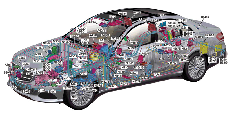
 shows the complexity of modern vehicle networks. Note that the CAN B (interior CAN) has two distribution blocks (X30/32 and X30/33), but only one has a ground connection: Find the small symbol on X30/33 (lower left) and see which other blocks also have grounds.")
This networking diagram for a new S-Class (222 chassis) shows the complexity of modern vehicle networks. Note that the CAN B (interior CAN) has two distribution blocks (X30/32 and X30/33), but only one has a ground connection: Find the small symbol on X30/33 (lower left) and see which other blocks also have grounds.
As an example, in a 126 chassis (S-Class from the ‘80s) several wires led from the power window switches in the center console to the motors in the doors. Each had to be relatively thick to handle the current, and there were at least eight of them to handle the four different motors. Add the multiple wires from the power seat switch and the in-door lighting, and the wiring harness soon became almost too thick to bend where it enters the door. In a 210 (E-Class from mid-’90s), there are just four wires: power, ground, and two CAN bus wires (named CAN-High and CAN-Low), a significant improvement.
A, B, or C
When first introduced, two different types of CAN buses were used: Class B and Class C. Class B CAN operates at lower speeds (83.3 or 125 kb/s) than Class C, allowing it to function even if one of the wires has no continuity. Class B CAN was used in the interior, since the communications demands were not as large. Class C was used for the Engine CAN bus, since the higher speeds (around 500 kb/s) were necessary to carry all the data.
More recently, all CAN buses have been moved over to Class C, starting in the early 2000s. From a diagnosis standpoint, the approach is the same; only some details of specific voltages are different. We’ll get into that in just a moment.
| Network | Bus Name | Speed (kBit/s) | Wire Colors (H-L) |
| CAN A | Telematics CAN | 125 | BK/WT – BK |
| CAN B | Interior CAN | 250 | BN/RD – BN |
| CAN C | Drivetrain CAN | 500 | BU/WT – BU |
| CAN D | Diagnosis CAN | 500 | GY/WT – GY |
| CAN E | Chassis CAN | 500 | GN/WT – GN |
|
Modern vehicles use Class C CAN networks exclusively, but some older models also used Class B networks. This table shows a few typical CAN buses and how the network speeds (and wire colors) can vary. The CAN High wire generally has the tracer stripe. |
|||
The details of how CAN works are somewhat complex, but for our purposes (fixing a problem) we don’t need to worry about most of all that. If you are really interested, WIS does a good job of explaining it, and the Internet has hundreds of articles on this topic. The general idea is that there are senders and receivers on the bus. When a message is sent onto the bus, every other CAN node on the bus hears it, but only the ones programmed to use a particular message will react to that message. If, for example, a power window switch sends the message “lower left front window,” only the left front Door Control Module will do anything about it, namely deliver power to the window motor to lower the window.
When troubleshooting, you need to consider that there are only three parts to the whole system: The sender, the receiver, and the wiring in-between. In every case, the problem is going to be with one or more of these elements.
 that is affecting the signals (arrows) causes the voltage to change in both wires at the same time. Since CAN only cares about the difference in voltage between the signals, this strong interference has virtually no effect on the bus performance.")
On this oscilloscope trace of a CAN bus in operation, we can see that the electromagnetic interference (EMI) that is affecting the signals (arrows) causes the voltage to change in both wires at the same time. Since CAN only cares about the difference in voltage between the signals, this strong interference has virtually no effect on the bus performance.
If you have XENTRY, you can watch the CAN bus to see if the sender is really sending a message, and you can operate the receiver’s circuitry to see if, when it receives the message, it can do what it is supposed to. If both are okay, the problem must be the in-between wiring.
CAN bus wiring is a little bit special: It uses two-wire differential-voltage signaling. What that means is that the same signal is sent over both of the wires, but one signal is inverted (flipped) from the other. The receiver doesn’t look at the voltage signal itself, but the difference between the voltage signals.
Why is that important? First, by looking at the differential voltage, any electromagnetic interference (EMI) that the wires might pick up has no effect, since both wires will get the same voltage noise signal. So if some kind of interference puts a 7 or 8V pulse onto both wires, the differential voltage between the two wires is still zero. In this way, CAN bus is nearly immune to EMI.
Second, if one of the wires in a Class B CAN bus is shorted to ground (or power), the voltage difference is still about the same as if the wire wasn’t shorted, so the message can still be read and understood. This makes the CAN bus fault-tolerant. As a case in point, we found a 210 E-Class where one of the CAN bus wires was shorted to ground by the left rear door control module while chasing down an intermittent no-crank condition. Turns out the car needed a new Electronic Ignition Switch (EIS) for the repair, but as far as we know that car is still driving around with that door module installed, because there were no symptoms and the customer didn’t think it necessary to replace it. A Class C CAN bus, which operates at higher speeds and is therefore less tolerant of faults, would not function in single-wire mode.

A typical CAN distribution block. This one does not have a ground wire.
Since every control unit hears every message on a given CAN bus, it stands to reason that they are all connected together. In some cases, Mercedes-Benz uses a solder splice to connect all the CAN-High and CAN-Low wires together, but Voltage Distribution Blocks are much more common. These blocks consist of several rows of two-pin connectors, with all the CAN-High pins connected together, and all the CAN-Low pins connected together.
This forms a so-called “Star” network, because if you stretch out the wires from the block in different directions they will form a kind of star. Contrast this with a “Linear” network where Node A connects to Node B, B to C, C to D and so on: This is how the D2B and MOST optical networks are connected. In a Linear network if a node fails, part of the network is cut off, while in a star network a node failure might have no impact (beyond the failed node).

Mercedes sells various adapters which allow easy connections to the CAN distribution blocks for diagnosis. There are a couple of different adapters like this available, all of them useful.
Those distribution blocks are important for you: They represent key points for CAN bus operation and offer a great opportunity for testing. Some of them are a challenge to get to, but many are located where access takes just a minute or two. Also note that these can fail: Many have a “terminating resistor” that is essential for proper bus operation, and if it fails it can bring the bus down.
In troubleshooting, our goal is to identify the problem without any doubt, using the least amount of effort. If we deconstruct a CAN bus into its parts, we find that it (like any network) consists of several “layers.” At the lowest level, we find the physical layer, which consists of things you can touch, see, and measure: wire, connectors, voltages, and the like. Above this layer are things like the data, network, session and application layers (and others), but we don’t care about these. Why not? Because there is nothing we can do about them if they have a problem.

Here we can see a group of four CAN voltage distribution blocks [2], located in the dash near the hood release handle [1]. The CAN bus physical layer, consisting of wires, connectors, and voltages, is the only part of the CAN bus that really matters for diagnosis.
That brings us to a key point about CAN diagnosis: You are only concerned with the physical layer. That means wires, connectors, and voltages. That really is all that can go wrong with a CAN bus.
As with any diagnosis, the first step is to identify all the symptoms. You already know how to do this: Ask the customer, and look at any fault codes that are present. For fault codes, don’t look at the systems that are complaining about the CAN bus, but look at who they are complaining about. Another thing is to look at any systems that are missing from the quick test, but you know are in the car. For example, if the instrument cluster doesn’t show up on a quick test, it’s obviously got a problem communicating.
With intermittents, try to reproduce the problem under the same operating conditions as the customer complained about. We want to nail this on the first try, if possible, and seeing it for yourself will help a lot.
With the symptoms and the wiring diagrams, the steps of a diagnosis are:
- Determine which CAN bus has the fault. Modern cars have dozens of buses, but they are not directly connected to each other, so any problems will be isolated to a single bus. Use the wiring diagrams to determine which CAN bus has the components affected.
- Determine electrically if the CAN bus is open or shorted. Again using the bus wiring diagram, find a place where you can measure the CAN bus voltages without disconnecting anything (so the system doesn’t reset and temporarily remove the fault). Try to avoid having to take the whole car apart for this stage of testing, since you know the voltage should be the same everywhere on the bus. For the interior bus, the overhead control panel (dome light) is a good choice. Measure the CAN High and CAN Low voltage relative to chassis ground. Mercedes-Benz recommends back-probing the connector, as long as the wires don’t have a seal that can be damaged.
- Determine which “branch”of the bus has the fault. We do this by disconnecting branches at a distribution block until the problem goes away. Instead of doing this one branch at a time, keep dividing the network in half to speed up the process.
- Determine if the fault is from wiring or a module. Disconnect the module at the far end from the distribution block, and carefully test the wiring for shorts (including to power and ground) and continuity. If the problem comes back only when the module is connected, suspect the module instead of the wiring.
Here is an exercise for you that will pay you back every time you need to check a CAN bus:
There are only so many ways a CAN bus physical layer can fail, as listed in the chart on Page 9. On a car that’s working fine, create each fault and read the CAN voltages, then write down your readings in the chart. What this does is give you a reference chart. If your problem car has a voltage that isn’t quite right, you’ve found the problem. You should repeat this on a few different CAN buses and make up a chart for each one, since some vehicles and buses will have different voltages.
| Fault Type | DC Voltage: CAN H to Ground |
DC Voltage: CAN L to Ground |
|
| No fault (normal) | 2.6-2.7 | 2.35 – 2.45 V | |
| CAN H shorted to Ground | 0.0 | 0.1 | |
| CAN H shorted to Power | 12 | 11.5 | |
| CAN L shorted to Ground | 0.2 | 0.0 | |
| CAN L shorted to Power | 11.5 | 12 | |
| CAN H shorted to CAN L | 2.3 | 2.3 | |
| CAN H Open | 0.0 | 2.4 | |
| CAN H and L Reversed | 2.4 | 2.7 | |
| CAN L Open | 2.7 | 0.0 | |
| Incorrect terminating resistor (<20 Ohms) |
2.55 | 2.45 | |
|
This chart shows the ways a CAN bus physical layer can fail, and we’ve written in some typical voltages you might see under those conditions. On a working car, create each fault and make your own chart. Later when diagnosing, the chart will point you to the exact kind of fault on the CAN bus just by reading the voltages. Different types of CAN bus, and in different models, may have different voltages, so make a few charts for yourself from different buses and models. |
|||
For example, if CAN High is shorted to ground, you’ll measure 0.0V and the chart will tell you exactly that. Realistically, over 95% of CAN bus problems can be found this way. Yes, for intermittents you might have to monitor the voltage for some time, but you WILL find it this way.
If we jump ahead for a moment, once we have found the problem, it becomes a matter of locating it. For this, we go to one of those distribution blocks and start measuring and isolating the individual bus lines going out to the various modules. For intermittents, this might take some time, but there’s no easier way. A broken or chafed wire, a damaged connector, or whatever, can be repaired once you locate it. For non-intermittent problems this is almost too easy. Disconnect one connector from a distribution block at a time to isolate the specific wires involved.
Now let’s talk about test equipment. For most problems, a voltmeter is all you’ll need. For those intermittent problems, a two-channel oscilloscope will really come in handy. A ‘scope is just a voltmeter that shows its measurements over time, so watching the ‘scope reading (trace) while driving will easily show when something changes for a tenth of a second.
 look at the signals (like this one) can show if the signals are getting distorted. Distorted signals usually point to a bad terminating resistor or corrosion at a connector messing with bus resistance.")
This shows a normal CAN bus signal as seen on an oscilloscope. In contrast to the slow-timebase testing described in the text, a fast-timebase (10 mSec) look at the signals (like this one) can show if the signals are getting distorted. Distorted signals usually point to a bad terminating resistor or corrosion at a connector messing with bus resistance.
You want to set your vertical (voltage) range so you can see CAN High and CAN Low as separate traces, usually around 1V per division (full height for most scopes is eight divisions). Then set your horizontal (time) range to about 1/2 or 1 second per division (most scopes have 10 horizontal divisions) so the trace stays on the screen for several seconds. A voltage that drops to zero for a fraction of a second will be really obvious.
If you are wary of oscilloscopes, there’s really nothing to be afraid of. You can get a nice 2- or 4-channel oscilloscope with a 10 MHz bandwidth (more than enough) for well under $400, particularly those that connect to a laptop computer via USB. Used scopes on eBay are a good choice as well, but older analog models usually can’t display a very slow trace, and don’t have any memory for later review. With a laptop model, you can drive alone and look at the data later, after you’ve seen the problem happen and don’t need to keep your eyes on the road.

This CAN distribution block has one connector with a third wire, connected to ground for the terminating resistor. Note the brown wire at upper left. If this becomes disconnected, the CAN signals will be distorted, which can only be seen with an oscilloscope. The blue wires indicate this is from the Chassis CAN.
From a practical point of view, the majority of problems we have seen are caused by damaged wires. Connectors sometimes get disconnected, perhaps partially, as well. In the case of a disconnected connector, only one control module (the disconnected one) will have a serious problem, but others may also have some impairment because they’re not getting messages from the disconnected one.
Rarely, but not unheard of, are the connector blocks. We mentioned the terminating resistors — these are essential to bus operation. With the bus asleep and not sending any messages (the voltages will go away), you should measure about 60 Ohms (for most CANs) between CAN High and CAN Low. Anything else indicates a problem. A very few control units have terminating resistors inside; mostly these are in the distribution blocks, but not every block has one.
You can tell if a block has a resistor by either one connector having three wires, or the symbol on the wiring diagram. Or, of course, by measuring the block with everything disconnected. Most CAN buses will work until the resistance from CAN high to CAN Low drops below about 16 Ohms.
Rarer still are control units that have gone bad, but this does happen every once in a long while.
We hope this brief explanation of the CAN Bus helps you time and again with squashing those networking gremlins.


0 Comments