
An essential part of the drive-by-wire and CAN concepts, it was very well engineered to begin with, and is even better now. But you’ve got to know how it fits into the big picture.
 So, you get behind the wheel of a car, your brain decides to move forward, and a bunch of neurotransmitters send a signal to the central nervous system. From that “digital” signal, a physical “analog” response takes over and commands the right leg and foot to push on the accelerator, which in turn is connected via a cable or linkage to the throttle plates of the engine, opening the way for air to enter the cylinders, and, with the addition of a little fuel and spark, voilà, the car accelerates.
This has worked well for a century or so with fairly trouble-free service except for the occasional worn-out linkage or cable, or one seizing up due to acting as a woefully-inadequate substitute electrical ground. So why change? The obvious answer is the efficiency made possible by modern technology. We are in the digital age and there is simply too much lost and unmonitored motion in the throttle cable setup. What the manufacturers are after is to make a vehicle’s powertrain characteristics seamlessly consistent irrespective of prevailing conditions, such as engine temperature, altitude, and accessory loads. Electronic throttle control is also working behind the scenes to dramatically improve the ease with which the driver can execute gear changes and deal with the dramatic torque fluctuations associated with rapid accelerations and decelerations. Electronic throttle control facilitates the integration of features such as cruise, traction , and stability control, and other dynamic systems that require torque management — the throttle can be moved irrespective of the position of the driver’s foot. ETC provides some benefit in areas such as air/fuel ratio control, exhaust emissions and fuel consumption reduction, and also works in concert with other technologies such as gasoline direct injection.
Early versions

Wiring damage in an early EA harness.
The first versions of electronic throttle actuation (ETA) were production-line “add on” systems. They utilized their own Electronic Control Module (ECM), so they didn’t require additional hardware (or programming) in the vehicle’s original ECM. Only minimal data went to the vehicle’s ECM via a serial link from the electronic throttle actuator control unit. Some Mercedes-Benz cars made from 1993 to 1995 had ETA problems. Most were due to shorted wiring inside the ETA loom, and others were internal component failures. When ETA fails, the car goes into the “Limp-in Mode.” Since the actuator is what controls the flow of intake air, when the system has a serious problem you will notice rough running, lack of power, and poor fuel economy.
In early 104 engines, the electronic accelerator (EA) operated in concert with acceleration slip regulation (ASR), and was designed to improve starting off and acceleration performance as well as driving stability. The components of this system include:
- Cruise control (CC) actuator
- Right and left EA/Idle Speed Control (ISC) actuators
- EA control module
- Set value potentiometer and actual value potentiometer incorporated into the accelerator pedal assembly
Also incorporated into the system are two safety controls:
- An idle speed safety contact, which signals the idle speed position of the throttle valve in the actuator to the EA control module. If the accelerator pedal is not depressed, the IS contact is closed if the signal from it is plausible — actuation to the fuel pump is enabled. The switch point of the idle speed safety contact is at a positioning angle of approximately three degrees above idle speed stop.
- A “slaved” safety contact signals the drive position of the throttle valve to the EA control module. This contact is open if the accelerator pedal is not depressed. When the accelerator pedal is depressed, it is closed. The slaved safety contact closes sooner than the idle speed safety contact opens, and an overlap takes place with the idle speed safety contact. In normal cases, one of the two contacts is always closed.

This is the flow chart for an early ETA system.
The functions of idle speed control, cruise control and electronic throttle control are integrated into the EA control module. This module is supplied with voltage at ignition ON. The position of the set-value potentiometer is changed with the accelerator pedal through the throttle control. The signal voltage of this potentiometer is passed on to the EA control module. The throttle valve position is tapped as a voltage at the actual value potentiometer and is supplied as an input signal to the EA control module.
 and back once again to idle. The blue trace shows a conventionally increasing voltage as the pedal is depressed, while the red trace operates over a lower voltage. Combined signals allow the control module to calculate a mean voltage output from the two signals. This allows the pedal position to be calculated with greater accuracy than when only a single voltage output is taken into consideration.")
In the waveform shown, the trace below shows the throttle moving from idle to WOT (Wide Open Throttle) and back once again to idle. The blue trace shows a conventionally increasing voltage as the pedal is depressed, while the red trace operates over a lower voltage. Combined signals allow the control module to calculate a mean voltage output from the two signals. This allows the pedal position to be calculated with greater accuracy than when only a single voltage output is taken into consideration.
The actuator motor for the throttle valve is operated through an output stage in the EA control module. The input signals supplied by the set-value and actual- value potentiometers are compared in the EA control module. If the two signals differ, the position of the throttle valve is corrected in line with the specified value. In contrast to the cruise control module, the EA module is able to control the throttle valve so as to open and close it irrespective of the position of the accelerator pedal.
New and improved
The improvements Mercedes-Benz engineers have made to the earlier systems can be categorized as simpler, yet more complex, at the same time. They are simpler in terms of incorporating the ECU into the electronic actuator system, but more complex in terms of functionality. As electronic controls in newer automobiles become more sophisticated, so does incorporating electronic throttle control into the equation. Now, the electronic accelerator function is integrated into and controlled by the ECU depending on driver input and the operating conditions, including the opening angle of the throttle valve.
Input signals for the electronic accelerator pedal are as follows:
- Accelerator pedal position
- Brake actuation (from the ESP control unit)
- Cruise control mode (also from the ESP control unit)
- Engine torque requests (via drivetrain CAN C and chassis CAN E)
- Gear ranges (over the electronic selector lever module control unit)
- Clutch operating system (in manual transmissions)
- Reverse travel (via the front SAM control unit with fuse and relay module)
A feature incorporated into this is known as throttle damping. This function closes the throttle valve up to the idle speed range with a time delay if the accelerator pedal is suddenly released. In this way, engine torque goes down slowly and the vehicle slows in a smoother fashion. Throttle damping makes its calculations based on the following input signals: change in speed of the accelerator pedal position, engine speed, coolant temperature, throttle valve position, and vehicle speed.
If the ME-SFI control unit recognizes that the vehicle is in reverse, the throttle valve will be opened more slowly and the maximum opening angle will be limited to about 50%. This function optimizes ride comfort with safety when backing up.
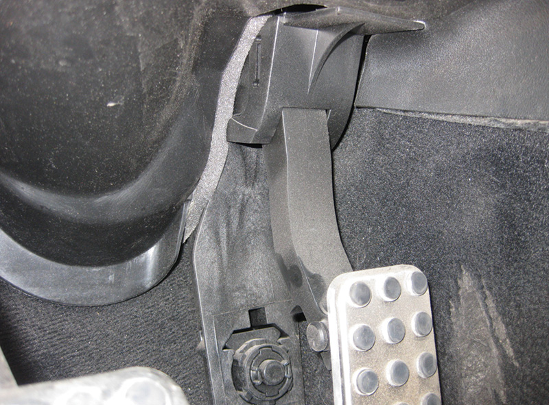
Function and operation
The position of the accelerator pedal and the speed at which the position of the accelerator pedal changes are transmitted to the accelerator pedal sensor located on the pedal itself. This sensor is located in the driver’s foot well right behind the pedal itself. It converts the mechanical movement of the pedal into an electrical voltage that corresponds to the accelerator pedal position. This is accomplished via a Hall-effect sensor. The accelerator pedal sensor consists of a shaft with a ring magnet. The magnet rotates in a printed circuit board with a stator in the two fixed Hall elements. This produces a change in the voltage. The Hall sensor sends an appropriate voltage signal to the ME-SFI control unit. If one of the signals from the Hall units should fail, the signal of the remaining Hall unit is used and the vehicle will go into limp-in mode.
The control unit then evaluates the voltage signal and actuates the throttle valve actuator on the basis of the performance map. The opening angle of the throttle valve is altered accordingly by the actuator motor in the throttle valve actuator. The opening angle is only determined by the accelerator pedal request if no limiting functions are active, such as the throttle damping mentioned above. The throttle valve actual value potentiometer reports the current throttle valve position to the ME-SFI control unit.
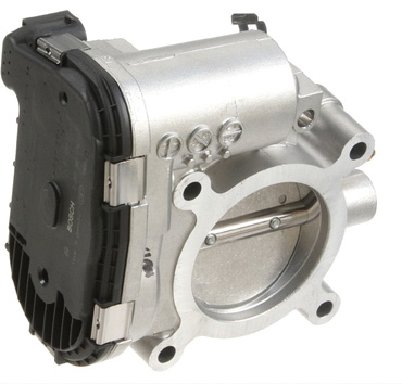
Throttle valve actuation
The throttle valve regulates the following functions: idle speed, driving mode, cruise control, and the electronic accelerator emergency mode. Its components consist of a throttle valve, return spring, mechanical stop, actuator motor transmission, and a setting shaft throttle valve.
 and back once again to idle. The blue trace shows a conventional rising voltage as the throttle butterfly is opened, while the red trace is inverted. The combined signals allow the PCM to calculate a mean voltage output from the two signals allowing the throttle butterfly position to be calculated with greater accuracy.")
The waveform of this newer system shows the throttle moving from idle to WOT (Wide Open Throttle) and back once again to idle. The blue trace shows a conventional rising voltage as the throttle butterfly is opened, while the red trace is inverted. The combined signals allow the PCM to calculate a mean voltage output from the two signals allowing the throttle butterfly position to be calculated with greater accuracy.
Also incorporated into modern ETAs is what’s known as adaptive control. Adaptation has been with us for some time now and incorporating it into the electronic throttle only makes sense. With the adaptive accelerator pedal, the ME-SFE control unit evaluates how the accelerator pedal is being actuated and switches between characteristic curves. After a 50% pedal travel about 80% of the engine load is released for sporty driver, and 40% of the load is released for the more conservative driver. There is no compensation built in for pedal travel above about 90%. An example of this adaptation might be after a more conservative driver has just maintained a long drive on a freeway, then the accelerator pedal must be pressed down unusually hard to obtain a higher acceleration level.
Additional functions of the electronic accelerator pedal include idle speed control, cruise control, torque interface, and emergency running. One note to observe: if the brake pedal is depressed, this always signals idle speed input.
Troubleshooting
Fault tracing the ETA is no different from that of any other system you may be called upon to troubleshoot. Good test equipment including XENTRY, or other factory-compatible scan tools, plus a good DMM (Digital Multi-Meter), and a lab scope are essentials. It would exhaust the amount of space that a magazine article covers to try to look at all the possible symptoms you might encounter, but here are a few scenarios:
MIL (Malfunction Indicator Lamp, also known as the Check Engine Light, or CEL) is on with DTC 1315.
- Test the battery. Low voltage on startup may cause throttle-sticking codes.
- Check for carbon build-up or sludge on the throttle plate, and clean as necessary. Retest for issue.
- Slowly move the throttle plate to check for a binding condition. Verify that the throttle plate springs back to the closed position. Replace the throttle body if you find that it’s faulty. Check this when temperatures are at fault-setting conditions.
- If no fault is found, verify that the engine actually reaches operating temperatures (85 – 90 deg. C). If not, replace the thermostat.
- Perform a reflash on the PCM with the latest software and software patch through your XENTRY machine.
- Perform a throttle body relearn with your scan tool.
The electronic throttle module is very dependable.
DTC 1315 is a common code in extremely cold temperatures. This code will set if the PCM requires high amperage (approximately 4A) to move the throttle plate when temps are below one deg. C (freezing). Regular oil changes and allowing the engine to warm up may keep these codes from originating. Also, make sure there is no moisture in the ductwork or throttle body itself that could cause icing. A thorough cleaning and a spray of WD-40 or the like can help eliminate moisture build-up.
Later models may turn up this fault, which is addressed in a Technical Service Bulletin:
“The engine diagnosis warning lamp — MIL/CEL — is on. One or more of the faults (P213500, P213629, or P213700) relating to the throttle valve actuator (M16/6) will be listed under Control unit / Fault is/are stored in the engine control unit (N3/10).
Cause: Contamination (even small, not really visible) of the contact surfaces between male and female pins at plug connectors could cause the fault to occur.
Remedy: If all the test steps stored in XENTRY Diagnostics have been performed and no component faults were found, the following work must be carried out:
- M276: Visually inspect contacts at throttle valve actuator (M16/6)
- M278: Visually inspect contacts X26 (intermediate connector M16/6 – N3/10) (see WIS reference for location)
- Visually inspect contacts at engine control unit (N3/10) connector M+F. If no noticeable problems are found, reconnect the connector and erase the fault. If the fault occurs again, or if this is a reoccurrence of the same problem, the relevant female contacts of the engine control unit connector must be replaced using Mercedes-Benz-approved harness repair materials and tools.
Other complaints you might see:
ESP warning message in the instrument cluster. One of the fault codes C219700 or 630900 is logged into the ESP control unit (N30/4). Cause: Engine control unit (N3/9 or N3/10) is receiving an implausible accelerator pedal signal. Remedy:
- Work through the guided test for fault code C219700 or 630900 in XENTRY
- Process all current and stored fault codes in control unit “Engine control system (N3/9 or N3/10)”
- Check component B37 (Accelerator pedal sensor).
- Check electrical lines and connectors from component B37 (Accelerator pedal sensor) to control unit (engine control system) for short circuit and open circuit.
- Check electrical connector at component B37 (Accelerator pedal sensor) for correct seating, contact and engagement (use only MLK1.2 pins for testing P/N A048 545 03 28).
- Check electrical connectors at control unit (engine control system) for damage, correct seating and correct locking (use only MLK1.2 pins for testing P/N A048 545 03 28).
- The fault may be caused by an interference source (for example, mobile phone or hands-free system), wiring susceptible to interference, or an incorrectly installed telephone system. Rectify cause of fault, do not replace control unit N30/4 (ESP control unit).
- If following the guided test is ineffective, replace the accelerator pedal module as per EPC (access by chassis number).
- If the problem has not been rectified after working through steps 1 through 3, please reference LI document LI54.18- P-059464.
When determining a faulty throttle body assembly or accelerator pedal position sensor, the replacement is fairly straightforward. Both are mostly just an unbolt and bolt-on operation. Many of the replacement units are plug-and-play, but you may find that some need to be coded. Check with XENTRY or WIS to confirm. It is always a good idea as well to check the SCN coding of the engine control unit to be sure it is of the latest release. Some complaints can be resolved by simply updating the software.
As you can see by just these few TSBs the electronic throttle actuator systems are amazing in their design, but require specialized equipment and training to service. Be sure you are up to date.
What’s next?
In our opening paragraphs, we asked how we evolved to this stage in throttle control, and now we must ask what’s next? Could it be possible that in the future we might just “think” we want the car to accelerate and somehow that information gets transmitted to the vehicle PCM? I know it sounds like Star Trek, but with autonomous vehicles on the horizon it’s not too far off base.
Download PDF 〉 [/s2Drip]


Awesome delivery of the information. A+