
Especially with direct injection, carbon build-up here is becoming a big issue. What does Mercedes-Benz recommend?

Believe it or not, the first automotive engine to use gasoline direct injection was the 1954 Mercedes-Benz Gullwing. It was a completely mechanical system, of course, and in the era of leaded gasoline, ignition points, and road draft tubes instead of PCV when nobody expected anything like the vehicular longevity we have today, carbon deposits were not considered a pressing problem.
In any discussion of intake, throttle body, and injector cleaning, we should split the conversation into two categories:
- Conventional port fuel-injected gasoline engines
- GDI (Gasoline Direct Injection) engines
Due to the different natures of these systems in terms of how the air/fuel mixture is introduced into the engine, they each have their own unique procedures in terms of prevention and cure of intake tract deposits.
As you know, in conventional port fuel-injection the throttle body controls the flow of air into the intake manifold and the injector nozzles are aimed directly at the backs of the intake valves. Over time, the throttle body, the manifold, the ports, and the valves build up a carbon and varnish residue that, if left unchecked, will end up diminishing performance. The reason this happens is twofold. One cause is when an engine shuts down, hot exhaust gases and unburned fuel float to the top of the engine. As the vapors bake in the heat, they form black sooty carbon deposits inside the throttle body and intake. The other cause is the PCV system, which continually introduces oil vapors. These condense on the insides of the throttle body and intake manifold disrupting optimum flow.

This cutaway of a late-model Mercedes-Benz cylinder head with GDI shows that injection occurs in the center of the combustion chamber, so continuous cleaning of the swirl chamber and intake valves with a spray of gasoline and its additives isn’t possible.
In a GDI engine, the fuel injectors have been moved from a position behind the intake valves to the combustion chambers themselves (hence “direct injection,” as most diesels have today). Since the injectors used to be in the intake runner, close to the intake valve, the gasoline with its additives would act as a cleaning agent that prevented, or at least reduced, the accumulation of oil and carbon deposits on the backs of the intake valves. That is no longer the case with GDI, so the PCV oil vapors condense and collect in the ports and on the valves much more rapidly — the typical timeframe for this to become bad enough to affect performance is 30,000 to 40,000 miles of use.
So what’s the big deal with carbon?

Carbon build-up can be huge, and very detrimental to performance
Carbon deposits contribute to abnormal combustion in several ways, but the most dramatic is the “sponge effect.” As the air/fuel mixture in the cylinder is compressed, the carbon has a tendency to absorb both oxygen and fuel. Once the spark fires, the flame front normally spreads through the chamber, consuming the charge. The build-up of carbon, however, has a tendency to extinguish the flame front and stifle combustion. This, combined with the lack of the air and fuel that has been soaked up, results in poor efficiency. This tends to affect performance, particularly during warm-up. A cold engine needs a relatively rich mixture, so absorbed fuel can result in a lean misfire.
When carbon deposits grow large, they can also upset the precisely-engineered pattern of air flow through the ports and in the combustion chamber.
Evolution of the GDI engine
While most conventional engines still use indirect port fuel injection, the world’s first gasoline engine with direct injection was the legendary 1954 Mercedes-Benz 300SL Gullwing. Since then, the company has pioneered direct injection for several high-efficiency European models, including the 2006 CLS350 CGI, powered by the world’s first gasoline engine with piezo-electric direct injection and spray-guided combustion. This advanced engine achieved 10 percent better fuel economy versus the normal V6 with port injection.
A number of 2012 Mercedes-Benz models are powered by engines that feature direct fuel injection. The new four-cylinder and V6 get better fuel economy while producing more pulling power – an impressive feat, considering that increasing either power or fuel economy usually decreases the other.
The new-generation SLK roadster, the new C-Class coupe, and the redesigned C-Class sedan are all available with a 1.8L inline four-cylinder engine (201 hp, 229 lb.-ft. of torque) that’s fitted with direct fuel injection and a turbocharger.
The recent GLE, the C- and E-Class lines, and the new SLK roadster can all be equipped with a 3.5L normally-aspirated V6 that produces 302 horsepower and 273 lb.-ft. utilizing multi-spark ignition as well as direct injection.
The new direct injection system
.")
The new piezo-ceramic fuel injector operates at seemingly impossible speeds (courtesy Robert Bosch).
The fuel system on the new four-cylinder and V6 engines represents the third generation of modern Mercedes-Benz gasoline direct injection systems. First used on Mercedes-Benz diesels, the electronic fuel injectors spray gasoline directly into the combustion chambers.
In addition, the new V6 makes use of industry-leading electronics technology that features a piezo-ceramic crystalline element in each fuel injector. The piezo crystal changes shape instantly when electrical current is applied, which makes it possible to design very sensitive and precise injection systems, including the ability to program several small injections with each piston stroke. This is especially impressive, considering that engines idle around 20 strokes per second, and at high speeds run at about 200 strokes per second.
This demonstrates the potential of the internal combustion engine for continued development and refinement. System pressures of electronic direct injection are similar to pre-common rail mechanical diesel injection systems – up to 2,840 psi.
Prevention and a huge maintenance factor
Since a major concern among engine manufacturers is carbon build-up caused by gasoline, Mercedes-Benz recommends the use of only “top tier” premium gasoline containing additives that retard the development of these deposits. This means fuels meeting ASTM standard D439. The octane rating must be at least 91. Spending time educating your customers will help ensure that they enjoy many trouble-free miles.
After an extended period of using fuels without high-quality additives, carbon deposits can lead to such symptoms as:
- Warm up hesitation or misfire
- Unstable idle
- Knocking or pinging
- Power loss
Mercedes-Benz recommends that no aftermarket fuel additives be used as they typically produce no measurable improvement and will only result in higher cost to the consumer.
Then there’s a large factor that’s not often mentioned: motor oil. Both the quality of the lubricant and the frequency of oil changes affect the formation of intake deposits in any engine, but especially in those with GDI. Those PCV vapors we mentioned earlier? They’re the culprit, and the use of only the highest-quality synthetic oil, and adherence to a strict fluid maintenance schedule will go a long way in preventing intake tract deposits.
Liquid methods
Routine cleaning of both types of injection systems and especially the direct-injected models will help prevent the formation of “hard” carbon deposits, which will be more difficult to remove at a later time. Although there’s really no scheduled interval for cleaning the intake tract, most experienced shops have found that on conventional fuel injected systems a 40K-mile interval is good, whereas with a GDI engine that number drops to 30K — and some say as often as every 20K.

A super-fine solvent spray mist can be introduced into the throttle body to clean the intake tract. It’s sensible maintenance.
Any good cleaning will start with inspection of the air filter and intake duct, being sure to clean and remove any debris in the air filter housing. Using a good quality chemical made specifically for intake, you can begin with cleaning the throttle body. There are several ways to go about this. One, of course, is to simply use a spray can with a nozzle straw, and scrub with a soft rag or nylon bristle brush. Be careful not to allow too much cleaner to pool inside the intake behind the throttle body, which can cause a hydraulic lock upon startup. Some techs like to place a rag or cloth behind the opening of the throttle to soak up the excess and then fish it out afterwards.
In cases of a really coked-up throttle, you will want to remove it for a more thorough cleaning along with the rest of the intake regardless of whether or not you are working on a conventional EFI or GDI, and you will need some specialized equipment.
The process involves a high-pressure nozzle that sprays a fine mist just ahead of the throttle plates and enters the engine while it’s running. You may be pleasantly surprised at how clean you will find the throttle and intake after the procedure. You can follow up with a fuel additive if the equipment maker recommends it. Using a borescope in the intake before and after can help you to see the results — you may even want the customer to take a look.
M272/273 intake flaps

This vehicle has an intermittent p2004 code, meaning the intake runner flap on bank 1 is sticking. The chemical cleaning procedure may be too late.
Some of the most common complaints associated with intake tract deposits will be found on the M272 and M273 engines. Excessive build-up in the intake may trigger any of the following codes:
- P2004 – Intake Manifold Runner Control Stuck Open Bank 1
- P2005 – Intake Manifold Runner Control Stuck Open Bank 2
- P2006 – Intake Manifold Runner Control Stuck Closed

This photo of the intake manifold runner control set-up shows the plastic levers that operate the flaps. If deposits jam movement, the levers may break.
The problem is caused by an air flap inside the intake manifold sticking, which causes the actuator arm to break. This results in dramatically deficient performance. There are repair kits with an improved arm, but they don’t correct the cause. Again, poor fuel quality and infrequent oil changes lead to the deposit build-up that causes the stuck flap and broken arm. Once the flap is stuck, the only proper repair is replacement of the intake manifold. Prevention with routine intake cleanings can prevent this from occurring and save your customer a large expense.
What about those “hard carbon” deposits?
In cases where the motorist hasn’t followed Mercedes-Benz fuel-use and oil-change recommendations, and has gone too long without routine intake tract cleaning, you may encounter deposits that will not come off with conventional chemical cleaning agents. Then, you’ll need to physically remove the carbon from the intake, especially the ports and the backs of the intake valves.
One approved process is walnut shell blasting. Walnut media is effective on carbon deposits and other dirt while not damaging the integrity of the substrate materials, especially aluminum. Unlike sand or glass beads, walnut shells are perfectly safe for the engine.
This procedure, however, requires removal of the intake manifold and enough room to attach the nozzle and vacuum hose. If the engine you are working on is too tightly packed for this to be performed in the car, you will have to remove the head and send it to a qualified machinist for full reconditioning, or see if your local Mercedes-Benz dealer’s parts department has a remanufactured head available.
Before you start with walnut shell blasting, you’ll still want to clean the “goo” out of the intake manifold. So, the above-mentioned chemical process would be beneficial prior to removing the manifold. Better yet, while the manifold is off you can disassemble it, remove any sensitive parts, and put it in your hot parts washer.

Here’s what you need to perform walnut shell blasting — not a big investment.
Walnut shell blasting equipment is available now at a reasonable price, so if you see enough high-mileage vehicles in your shop, you might consider this purchase. You will also need a good shop vacuum — large, and with good filtration to keep dust out of the air. Don’t forget to wear eye, hand, hearing, and respiratory protection. Your air compressor needs sufficient capacity to provide a continuous 100 psi.
Begin by opening the port at the top of the blaster canister and adding the media until it’s about 3/4 full, thus leaving some space for compressed air (keep your media storage bag sealed up tight as even a little bit of moisture will cause clumping). Refit the canister fill top, and keep all valves closed until you’re ready to start the procedure. Also, make sure you’ve drained any water out of the compressed air supply. Set the tool pressure to about 100psi, then open the air valve. Next, open the lower tank siphon hose and the feed hose valve for the media blasting nozzle.

You may need to modify the adaptor to prevent blow-back of the media.
Place the adaptor into the swirl chamber of the cylinder head (intake side, of course). In some cases, the adapter will be smaller than the port it is being inserted into. If you begin to blast with an air gap around the adapter, a lot of “blow back” will occur. The idea is to seal off the chamber so the media goes in and not back at you. You may need to make some modifications to the nozzle.

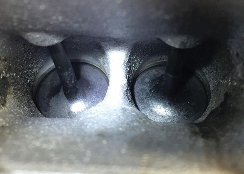
Could this look any worse? Driveability and performance down, emissions up.
Extremely important! Before you begin blasting, be absolutely certain both valves in the chamber you are working on are closed. Otherwise, you risk filling up the cylinder with walnut shells.
Connect the shop vac, then insert the adapter into the swirl chamber with the nozzle valve still closed. Before you begin blasting, turn on the shop vac and make sure there are no obstructions. The idea is that as you blast the vacuum is constantly removing the media and the carbon deposits with it.
What a difference!
Work in short blasts of 10 to 15 seconds. Move the nozzle in and out and around in a circle to clean as much surface area as possible per blast. Close the nozzle valve and allow the vacuum to run for a few more seconds to clear the swirl chamber.
While this process produces excellent results, it should be obvious that convincing your customers to use top-tier gasoline and to follow Mercedes-Benz’s recommendations where oil quality and maintenance are concerned will eventually prove to them that you give excellent advice.


0 Comments