
An introduction to the tools and techniques necessary to perform ADAS calibration on Toyota vehicles for radar, cameras, and sonar.
Do you repair Advanced Driver Assistance Systems (ADAS)? Many independent shops don’t, but why not? Reasons may include complexity, cost for equipment or “It’s only for body shops.”
Although the systems are complex, they’re not any more so than many other systems you repair, and Toyota provides all information you’ll need to be successful. Does it cost a lot for equipment? Not really. You can tool up for under $2,000, even less if you already have a Techstream. And as for being only for body shops, if you do cooling system work, air conditioning, headlights, mirrors, and many other seemingly mechanical jobs, you’ll need to deal with ADAS.
This article will cover what equipment you’ll need to get started, how to find the information you’ll need on TIS and a couple of real-world examples of radar calibration.
What You’ll Need to Get Started
Many aftermarket companies offer ADAS calibration systems with software and targets for a wide range of vehicle applications. One of these systems might seem very attractive for a shop working on multiple makes.
However, here are some things to consider before going with an aftermarket solution. There are some differences in the aftermarket systems. For instance, some alter target size to reduce the space needed for calibration. This might seem like a plus, but will it work properly? You’d also need to trust that the aftermarket company made no coding errors and has tested the system rigorously.
Toyota hasn’t tested or approved any of these aftermarket ADAS calibration systems. Therefore, the safest choice for calibrating Toyota vehicles is the Toyota scan tool (Techstream) and the “special service tools” (SSTs) listed in the service manual. Luckily, the Techstream and SSTs you’ll need are very reasonably priced.
Tooling Up Isn’t Costly
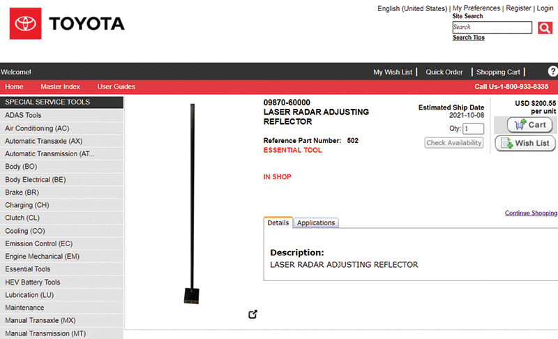
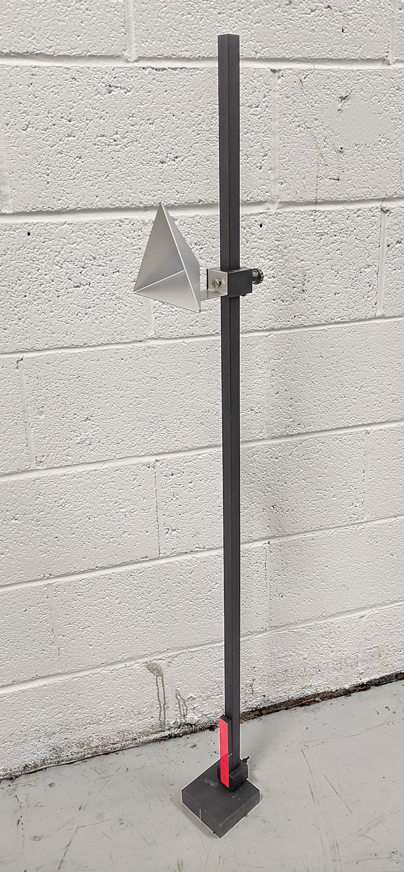
With only two SSTs, a Techstream, and some commonly available tools, you will be able to do radar and camera calibrations for many types of Toyota vehicles. The first SST is the Radar Adjusting Stand, part number 09870-60000. This is necessary for “Front Recognition Camera” (FRC) calibration and radar calibration. The other SST is the Reflector Target, part number 09870-60040, which is necessary for radar calibration.
These tools are available from Toyota’s Service Solutions website toyota.service-solutions.com. Depending on availability orders can take six weeks or more for delivery, so it’s best to order before you need them.
The Radar Adjusting Stand includes a small red reflector used for older laser cruise control systems. The reflector target for radar calibration is a cone shaped metal trihedral that is used for calibrating the millimeter wave radar forward distance sensors and blind spot monitor sensor.
It’s All in the Details
Harvey S. Firestone, who founded the Firestone Tire and Rubber Company in 1900, said “Success is the sum of details.” There are no truer words when referring to calibrations. A successful calibration requires close attention to multiple details throughout the entire procedure. This is a time to sweat the small stuff. A few millimeters can mean the difference between a successful or failed calibration. A few millimeters might also mean avoiding a collision.
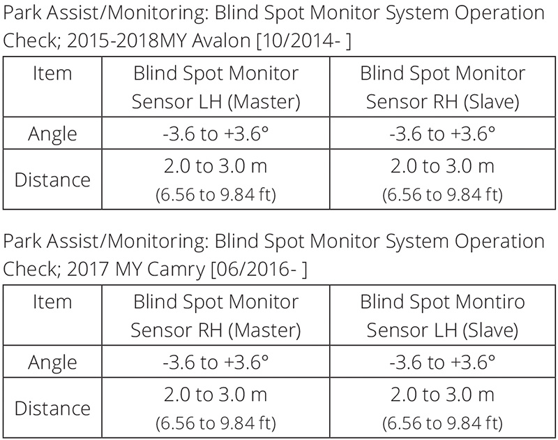
Don’t assume anything during the calibration process. Measurements, special service tools, or target placements can change from one model to the next or from one year to the next. For example, on the 2017 model year the Blind Spot Monitor master radar sensor is on the left-hand side for the Avalon, but the master radar sensor is on the right-hand side for the Camry. Making assumptions or skimming over the procedure could lead to trying to calibrate the wrong Blind Spot Monitor radar sensor on the vehicle.
Technical service bulletins and recalls should always be checked as one of the first steps in the process. Toyota has many technical service bulletins that are specific to one vehicle model, as well as general bulletins or “tech tips” that give best practices or additional information about radar or camera calibrations.
For example, Tech Tip T-TT-0603-20, “Millimeter Wave Radar Sensor Floor Slope Compensation,” details how to perform a calibration when a level floor surface is not available. Technical Service Bulletin T-SB-0184-17, “Toyota Safety Sense Front Camera Optical Axis Learning Information,” offers precautions and useful tips when adjusting the windshield mounted forward facing camera.
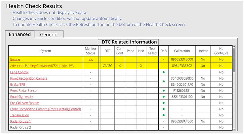
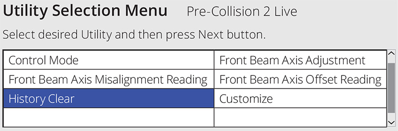
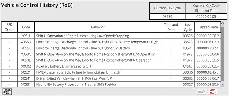
Even after a calibration is completed and successful, attention to detail needs to remain high. On certain vehicles equipped with Toyota Safety Sense (TSS), the Vehicle Control History needs to be cleared after a calibration is performed. Vehicle Control History is notated by RoB and a green dot on the Health Check Results (shown on previous page).
Vehicle Control History (VCH) is a Toyota-specific function that records data during a variety of events across multiple modules. First introduced with the 2013 RAV4, VCH has been integrated into more and more Toyota models throughout the years. VCH is similar to Mode 02 Freeze Frame, except a DTC does not need to be set for data to be recorded. The events that get recorded vary by model and year, but can include heavy acceleration, ABS activation, and low voltage conditions. The technology has evolved to include recording images and data from the radar and cameras equipped on the vehicle as well.
Clearing fault codes in a module or from the Health Check results screen does not clear the Vehicle Control History data. The RoB data needs to be cleared from each module individually. This is done through the Utilities tab after the desired module has been selected. Once on the Utilities screen, the History Clear tab can be selected. Now all the recorded events are listed, and time stamped (see images below). There is a clear memory option at the bottom left of the screen.
This final step of clearing the Vehicle Control History is easy to overlook, and adds additional time to the process, but it is required before the vehicle is returned to the owner.
Front Recognition Camera Adjustment
To adjust the Front Recognition Camera, you will need to print targets available on TIS, mount them to a cardboard backing, then attach them to the Radar Reflector stand. The target will need to be moved to three locations during the calibration. You will need to lay out these locations using basic tools like a measuring tape, plumb bob, string, tape, and a marker.
Each vehicle will be different, checking TIS for information before beginning a calibration is mandatory. For a generic overview of the FRC calibration process, watch the video titled “Front Recognition Camera Adjustment and Calibration” in the Technical Training area of TIS.
For important vehicle-specific information, search TIS for “before starting adjustment” (with the quotes for an exact phrase search). This document will save you from frustration and wasted time. You’ll find the adjustment procedure will be the next document in the table of contents, titled “Adjustment.”
Millimeter Wave Radar Sensor Adjustment
Radar sensor adjustment is similar to FRC adjustment, but instead of using printed targets, you’ll need to use the radar reflector, part number 09870-60040. Also, it’s only necessary to place the reflector in one location during the front sensor calibration.
Case Study: 2018 Tacoma Radar Sensor Adjustment
Since first being introduced in 1995 the Toyota Tacoma has changed a great deal. The truck was born out of the Toyota Hilux and was originally a compact pickup. Now in its third generation the Tacoma has grown into the midsized truck category. Sales have been strong throughout the years and that has continued with the 2020 and 2021 model years. These latest Tacoma trucks are loaded with technology, including front distance radar sensors as well as forward and rear facing cameras.
The following is a walk-through of the front millimeter wave radar sensor calibration on a 2018 Tacoma. The Dynamic Radar Cruise Control and the Pre-Collision System both rely on the front radar sensor.
Start by verifying correct tire pressures, performing a pre-scan of the vehicle, and visually inspecting for any modifications which could affect the system being calibrated. Running a Health Check with Techstream will identify any current or history faults, open recalls, or software updates. There’s no point in starting a calibration if the vehicle has a fault that needs repair.
Carefully review service information for the calibration procedure and for any Technical Service Bulletins. The 2018 Tacoma has two relevant service bulletins. T‑SB‑0059‑18 outlines customizable features for the Pre-Collision System related to off road or special condition driving, and T-SB-0026-20 has software programming to permanently disable the Pre-Collision System and Dynamic Radar Cruise Control on vehicles with modifications.
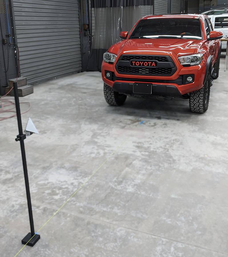
The target placement is straightforward. Using a plumb bob and string or laser level the center line of the truck is determined. Then the Radar Adjusting Stand with Reflector is placed 3000 mm in front of the vehicle.
The height of the Reflector depends on what grille type the truck is equipped with. There are three different grille designs based on the trim and option packages that the truck was built with. Each of the three grille types has a specific height for the reflector that corresponds with the front radar sensor.
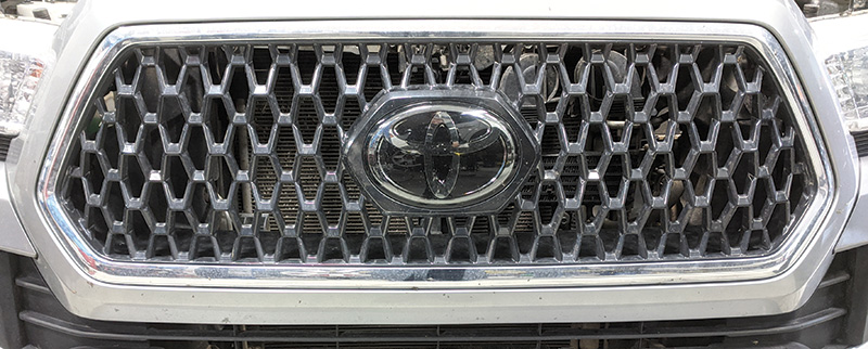
Carefully identify which grille type the truck is equipped with and set the reflector to the correct height. Using an incorrect measurement will result in a failed calibration or potentially a misaligned radar unit.
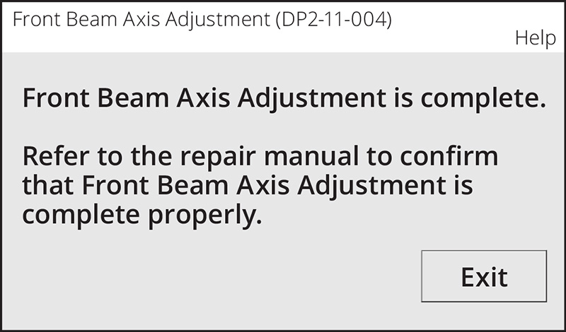
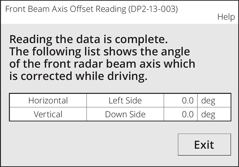
With the target in place, cruise control on, and Techstream connected to the vehicle, select the Utilities tab in the Pre-Collision 2 module. Follow the on-screen prompts and run the Front Beam Axis Adjustment followed by the Front Beam Axis Misalignment Reading and finally the Front Beam Axis Offset Reading. After the Axis Beam Adjustment completes successfully and the Misalignment and Offset Readings are within range, the calibration is complete. Confirm the correct measurements and reflector height if the readings are out of range.
This Tacoma does not need the Vehicle Control History memory cleared, so that step can be skipped. Finally, the vehicle should be road tested to confirm correct operation of the Dynamic Radar Cruise Control, along with a post vehicle scan to verify there are no remaining fault codes.
Case Study: Modified 2021 Toyota 4-Runner
The automobile has always been a symbol of independence and freedom. This sense of freedom has naturally led to customizing vehicles, and trucks most of all. From oversized tires, lift kits, winches, tow bars, brush-guards, aftermarket grilles and lighting kits the customization options are limitless. These customizations wreak havoc on the calibration process, however. Altering a vehicle’s ride height or obstructing a radar sensor or camera will make the calibration process impossible to complete.
This was certainly the case with the following 2021 4-Runner that needed the Front Distance Radar calibrated. The vehicle had been in a minor collision and the front bumper was removed to be repaired and repainted. Removal of the front bumper and grille requires that the radar sensor be recalibrated.
The pre-scan for the vehicle was clear and there were no warning lights displayed. An overall visual inspection of the vehicle raised some concerns though.
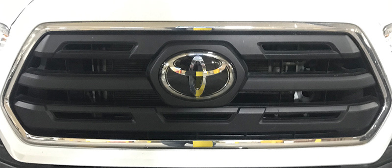
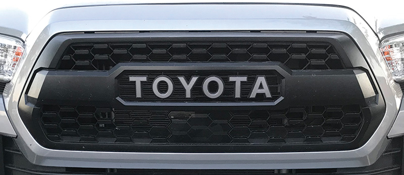
This 4-Runner originally came with P265 70 17 tires from the factory, but it now had LT285 70 17 tires installed. The grille had also been replaced with an aftermarket grille. Aftermarket grilles are becoming common place on these trucks, in part because an OEM TRD grille can only be ordered from the dealer with an appropriate VIN number.
These aftermarket parts are not always made to the same exacting standards that are required for radar or camera systems. The best option is stay with the OE grille with which the vehicle came equipped.
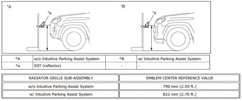
The procedure for this 4-Runner has two heights at which the reflector target can be placed based on whether the Parking Assist System option is present or not.
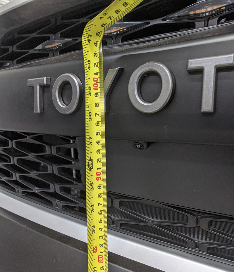
With the oversized tires and aftermarket grille the center measurement of the radar unit on this 4-Runner was 910 mm. This measurement is close to 100 mm above the Reference Value in the service procedure. The radar sensor cannot be properly calibrated in this condition.
Service information does not state that the target height can be changed based on oversized tires, a body or suspension lift, or an aftermarket grille. This vehicle is a case for recommending the software programming that permanently disables the radar sensor.
Typically, if a software update ends with a damaged or ‘bricked’ module, something went terribly wrong. That’s not the case for TSB T-SB-0026-20. This TSB has updated software that permanently disables the front radar module. This may seem extreme, but that’s what Toyota recommends for modified vehicles.
These are just a few examples of radar calibrations and the different issues that can arise. The “secret” to success is very simple. Read carefully, follow instructions, and pay close attention to the details. It may seem intimidating because it’s new, but it’s not difficult. You can do it.
0 Comments