
Mercedes-Benz charging systems are largely self-contained. Here’s how they work, what the individual components do and ways to test and repair the system when there’s a problem.
Whatever we say about charging systems, we’re talking about electrons. Swarms of them, trillions, quintillions – zillions. Electrical current is electrons moving; static electricity is electrons swarming and damming in one place or on one surface, separated from another where they don’t. When electrons move, you have electric current; when a lot of them move, you have a lot of current. When electrons pile up behind a resistance or an insulator, you have voltage; and a lot of them mean a lot of voltage.
|


The charging system output arises in the output coils of the stator, built into the case. The armature spins inside this ring, turning its magnetic field as it spins. The energy delivered to the armature shaft from the crankshaft pulley provides the force needed to pull the magnetic fields through the coils and produce the current.
A charging system makes use of two properties of electrons: They are directly connected to magnetism, both as cause and as effect – we’ll see more of this shortly – and they move freely through most metals. For all practical purposes, every electron in a chunk of metal can be an electron in any of the atoms of that same chunk. This ready capacity for electrons to move throughout it is, obviously, what makes metal electrically conductive. Materials that hold electrons more or less firmly locked in place in their individual atomic shells are insulators. A charging system uses each of these properties.
The connection between electricity and magnetism is the basis of the charging system. Just as a farmer might save a certain portion of this year’s crop as seed for next year, the charging system uses a certain proportion of the available electric current to make more. It doesn’t work by magic multiplication, of course; it isn’t a ‘perpetual-motion’ or a ‘free-energy’ machine. Next year’s farm crop derives most of its growth from the nutrients it draws from the soil. The next minute’s electric current derives most of its power from the mechanical torque energy delivered from the crankshaft through the accessory drive belt, factored by the electromagnetism built by a small portion of this minute’s electric current. Next year’s crop will grow with sun, rain and soil. The next minute’s electric current finally derives from the rendered dinosaur remains back in the tank, burning in the combustion chambers and driving the crankshaft.
Current Mercedes-Benz charging systems are almost entirely internal to the alternator, which contains the regulator internally and which does not connect to the rest of the vehicle’s electric system except as a source of power.
Current Affairs
Depending on how alert or provident the car owner is, the first symptom of a charging system problem may be the indicator light on the dash, or it could be a dead battery preventing the starter from cranking the engine to work.

The strap on one side of the regulator serves both as the voltage sampling probe and the source of energy for the magnetic field. This current passes through the brushes and through the field coil, building or reducing the spinning magnetic field as needed.
The alternators on Mercedes-Benz cars tend to last a long time before they need repair or replacement, and on some models removal is not a perfunctory task. If there is a charging problem, chances are at least even that the cause is something external to the alternator. So the first step in diagnosis of a charging system problem is to determine whether the problem lies with the alternator or elsewhere. You have the advantage that the charging systems on these cars are self-contained. They do not depend on the car’s main computer to regulate the alternator’s voltage output. The charging system is independent of the rest of the electrical system.

The regulator bolts to the alternator case. Its internal circuitry detects the difference between output voltage and the case, and its power transistor turns on and off to energize the field.
On all Mercedes-Benz models for many years the voltage regulator is internal to the alternator (often called a generator in the service literature), but much older vehicles had external voltage regulators. Even longer back, Mercedes-Benz cars, like all others, used direct-current generators. With such older models, contact Mercedes-Benz USA for vintage car technical information. The company can provide service and mechanical detail on cars dating back over 50 years.
The Box of Volts
Batteries often have shorter useful lives than alternators, and they are always (well, almost always) easier to work on. Right after your overall visual inspection confirming the presence and condition of the accessory drive belt and the main electrical cables, gradually bring the battery to full charge. Once it cools from your recharge, check the specific gravity of the battery acid with a suitable tool and check the open-circuit, unloaded voltage, which should be just over 12 volts. Then run a battery load test with the proper equipment, to see whether it retains the minimum voltage under the equivalent of cranking. A battery that can’t hold a charge is not only a problem itself; if it has an internal short, that can mean the alternator works at such a high output level that its useful life shortens, as well.
Generators and AlternatorsEarly charging systems used direct-current generators, which differed from present alternators in that the current was produced in the generator’s spinning armature and collected from a slotted bank of collectors called the commutator. The direct-current generator had brushes, but they had to carry not the relatively small amperage of the current creating the magnetic field but the full output of the generator itself. The field coils received the ‘seed’ current from the voltage regulator to keep the output within a proper voltage range. But sparking and heat from the higher current and the mechanical abrasion of the slotted commutator meant shorter useful life for the brushes in the direct-current generator. The diode, a solid-state, one-way ‘valve’ for electric current, allowed invention of the alternator. Now the electromagnetic field built by the return current from the voltage regulator could spin, generating current in the stationary stator windings, from which the output current flows. Of course, as a magnetic field spins, north and south magnetic poles follow one another in rapid succession, reversing polarity and thus the direction of electron flow. But the diodes work even more quickly and stop the flow of current when the voltage reverses. A direct-current generator looks very much like an electric motor, like a starter (except that starter motors don’t run long enough to require cooling air apertures). And, in fact, every such motor can become a generator and vice-versa. Something that looks much like an alternator is the industrial three-phase, alternating current electric motor, which does not even require small brushes for its armature because the current can be externally induced. To make things more confusing, however, carmakers have chosen in the last few years to call everything that provides the power for the charging system a generator, whether it is the usual alternator or an old-fashioned direct-current generator. But don’t get so confused you try to find a commutator in one of today’s generators – oops! I mean alternators… no generators. Well, you get the point. |
A reverse problem happens occasionally: If a voltage regulator overcharges the battery, not only should you replace the regulator (and for that matter, the entire alternator, as we’ll see below), but the battery may have suffered internal damage, including warped or cracked plates. If an overcharge went on long enough to electrolyze battery acid below the tops of the plates, this has almost certainly occurred. Experience shows that in such cases, it is prudent to check the insulation on the alternator’s output cable. If it shows signs of heat or even melting, replace it immediately along with the alternator and the battery.
Often people describe something as a charging system problem that actually results from a key-off current draw on the battery. This could be anything from a trunk light that fails to turn off when the lid is closed (climb in and look) or a closing-assist system that can’t quite latch the door or trunk, to anything else that continues to pull current from the battery.
The test for this is no longer as simple as it once was. Of course, you disconnect the battery and measure how much current flows through a jumper. If your clamp-on ammeter doesn’t register in the low ranges (well below one amp) needed for this test, coil your jumper wire in a circle ten times around. When you put the coil in your pickup clamp, it will multiply the tested current by ten, one for each winding of the wire.
The problem is, no modern car ever shuts everything off altogether. The engine management computer retains its electronic memory; the alarm system maintains its vigilance; the radio, seat adjustment and climate controls keep track of their settings; the central locking system stays awake, waiting for the owner’s flashed infrared signal to pop up the locks. All of these systems together don’t add up to even a consistent one-amp draw, or the car would be very hard to start after a few days unused, standing in the winter cold. The precise amount of the standby current draw is not an available specification because there are so many car models and accessory sets, but it’s worth while checking a few cars at random just to get a sense of what range of draw to expect.
Assuming everything is working properly, this rest current, called the “parasitic draw,” is much less than the internal current drain in a battery. Eddy currents form on and between the plates of a battery, currents which will inevitably discharge the battery over several weeks. There is really no method, other than fitting the car with a trickle-charger, which could prevent that. You can argue, of course, that if a person only needs to start his car every few weeks, he really doesn’t need to start a car at all.

Even on an inline six-cylinder engine, it can be difficult to remove the alternator if there is a charging problem. V-form engines present even greater access challenges. It is thus good practice to determine as clearly as possible whether a charging problem comes from the alternator or some external source, like a defective battery, a parasitic draw or a high-resistance connection.
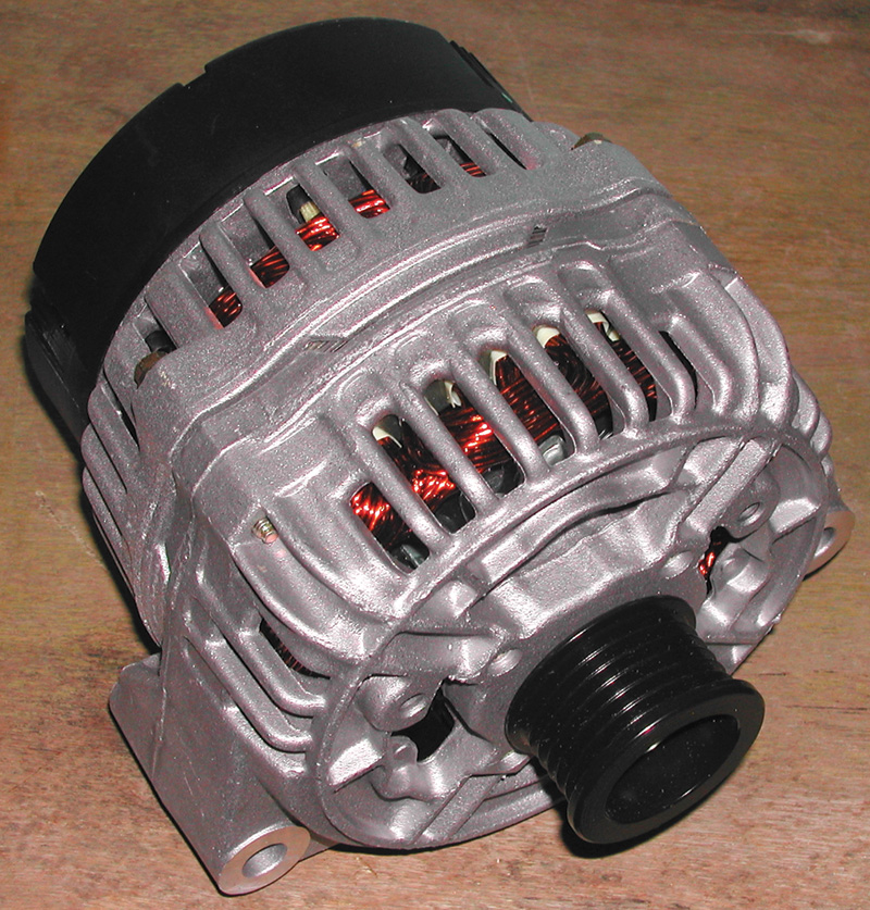
The Box of AmpsThe alternator is a round steel and aluminum and copper box that uses some of the smallest and some of the largest things in the universe to push or pull electrons along the wires we want them to travel. |
Resistances
If the battery is satisfactory and if the alternator is working properly, the charging system may still not work properly if there is resistance in the connections from the alternator to the battery and to the chassis ground. The most obvious of these connections is the output cable, going from the alternator output post to the battery terminal. But in electrical terms, it’s also the least likely to have resistance problems. In fact, every connection in a circuit is equally important, including the connections between the battery posts and the cable clamps, including the connection between the alternator housing and its bracket to the engine ground. Resistance at any point is resistance to the circuit as a whole.
The best way to discover such a problem is with voltage-drop tests. For these tests, however, it is again critical to have a fully charged battery and to run your tests under normal current conditions. Absent these, there is no way to tell whether your results are significant or not.
The test points do not have to be at points just opposite the connection. For instance, to test the connection between the alternator bracket and the engine block, you need only touch the bracket with one multimeter probe wherever it’s convenient. The other can touch the engine block anywhere at all. You may safely assume good electrical continuity through the block casting (otherwise there would be more serious, and more obvious, running problems than those involved with a charging system). Whether cranking, running or off, the voltage difference between the mounting bracket and the block at any point should be zero. The same should of course be true of the voltage between the alternator case itself and the block.

Inside the alternator is the rotating armature, supported at either end by bearings, with a field coil powered through the slip rings and ferrous metal ‘fingers’ that focus the magnetic field produced by the field coil. The centrifugal fan draws cooling air through the alternator.
The voltage regulator, internal to the alternator in all remotely modern Mercedes-Benz cars, maintains the output voltage at a constant 13 to 14.5 volts between the output post and the alternator case, which it takes as vehicle ground. Any resistance on either the positive or negative side of the charging circuit reduces the effective charging voltage below this, the amount of the reduction depending on the resistance and the current flow. Check ‘em.

With the regulator and brushes removed, the slip rings are visible surrounded by the rectifier. The tab to the right provides output voltage to the regulator.
Inside the Coils
What’s going on in the alternator, with its zillions of electrons and single (but very complex) magnetic field, or complex wrinkle of The Magnetic Field?
There are three wound coils in the outer case of the alternator, joined through the rectifier or diode cluster to the output post and at the other end to ground. The geometry of these windings is such that if magnetic fields forcibly spin within them, electric voltage appears and thus current flows in the windings; and the diodes will convert them to a direct-current output with an output voltage ripple corresponding approximately to the system load.
The real source of the electrical energy the alternator produces comes from the mechanical energy the engine puts in, through the front pulley. Don’t overlook drive pulley problems, therefore. A loose or glazed drive belt will not necessarily make noise. Check it for tension and for enough friction to grip the pulley. There have even been rare cases of pulleys that work themselves loose on the armature shaft, turning the alternator either very slowly or not at all but fooling someone who just tugs once or twice at the drivebelt to see whether it is tight.
The rectifier consists of the set of power diodes at the ends of the alternator stator windings that allow current to flow in the desired direction and block it when it reverses. These are solid-state devices with no mechanical internals. A defective rectifier, one with shorted or open diodes, means replacing the alternator.
Inside the alternator is the armature, a special multiple-pole electromagnet consisting of the electric coil that energizes it, a shaft that constitutes the center of the magnet and two opposite poles with opposing fingers, making the lines of electromagnetic force. ‘Seed’ current from the voltage regulator flows through the armature’s windings building magnetic fields of whatever strength is needed to keep the output voltage within the specified 13- to 14.5-volt range.
This current, the field current, enters and exits the armature through the two slip rings at one end of the shaft. Each ring is electrically connected to one end of the field coil around the armature shaft. You should, thus, always find continuity if you measure from one slip ring to the other, and you should never find continuity from a slip ring to the shaft itself, which grounds through the bearings to the case.
The amount of current through the field depends on what the voltage regulator senses is required to keep the charge high enough. Many factors, including the battery’s state of charge, the number of electrical consumers like blowers and lights and even the ambient temperature, affect this. The regulator never goes to the extent of a once-popular diagnostic test: full-fielding. This meant running full system current through the alternator field to distinguish between an alternator and a regulator problem. It was more accurately an electrical-abuse test: If the alternator could survive full-fielding, it was probably OK at least in the short run. Most modern alternators are now designed to prevent full-fielding.
The regulator itself consists of a microprocessor/power transistor that converts input from ground and power to output through the field coils. The lower the output voltage, the higher the field current and vice-versa. This keeps the output voltage constant. The regulator is one unit with the carbon brushes that contact the armature’s slip rings. These are items that wear out, eventually. It is possible to replace the regulator/brush unit individually rather than the alternator complete, but many dealers find that other wear elements of the alternator, such as the bearings on either end of the armature, have a similar useful life. They argue that replacement of the alternator complete not only reduces the chances of a comeback, but also turns out more economical over the useful life of the vehicle.


0 Comments