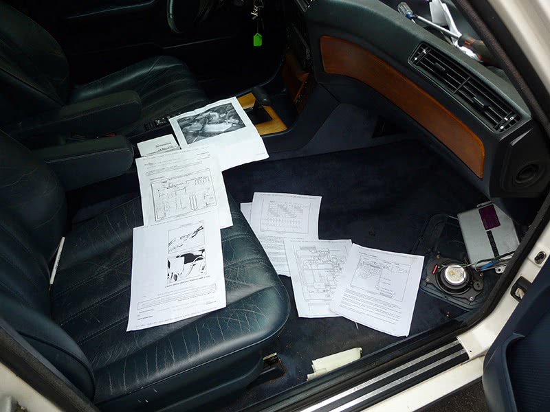
I was called to a shop for a no-start on a 1987 BMW 735i (Figure 1). It was towed in — no spark and no injection pulse will do that. The techs tried replacing parts that they felt were common pattern failures in this particular vehicle.This included a crank sensor, cam sensor, and even a used PCM. They had obviously tried to gather information on the operation of the fuel injection system — they were sifting through a big pile of printouts (Figure2). They were very limited on diagnostic tests, however, because this car had no diagnostic connector for pulling codes or using a scan tool view the datastream, so it was hard for them to get a sense of direction. They finally decided to call me in for technical assistance.
This was definitely old-school technology and did not even have OBD I. I could see it was going to give me a run for my money because without datastream or trouble codes I was going to have to spend some time reading wiring diagrams and trying to understand how to perform pinout checks directly at the PCM connector to guarantee complete tests of each computer circuit. I was also going to have to think about voltage values of sensor signals and the different thresholds they achieve under many different operating conditions. This is where a good scope or a graphing multi-meter comes into play because certain sensors create fast signal outputs that would need to be viewed as a waveform pattern over time to validate their integrity.
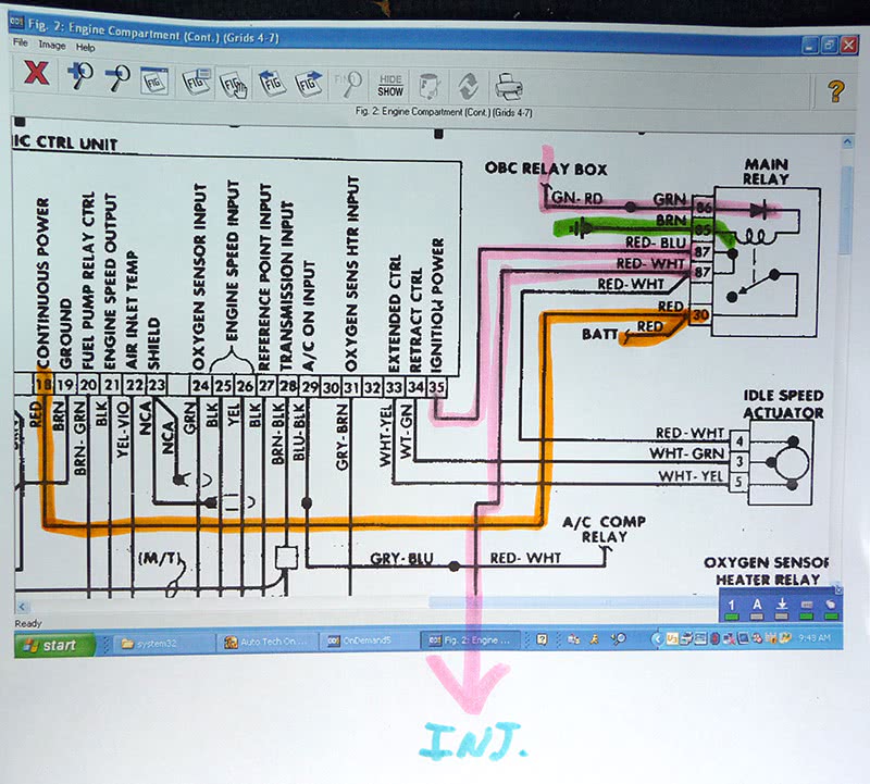
I needed to lay out a complete diagnostic routine for testing the pins at the Powertrain Control Module, so I printed out a diagram and started color coding it so I could mentally flow the circuits required to achieve spark and injection pulse (Figure #3). I applied a color-coding method I have been using for many years to help me relate to computer circuits. I traced all grounds with green, battery feed with orange, and ignition feed with pink. I then traced the dynamic sensors such as those for crank and cam position with yellow, and, lastly, the driver circuits such as ignition coil and injectors with blue.
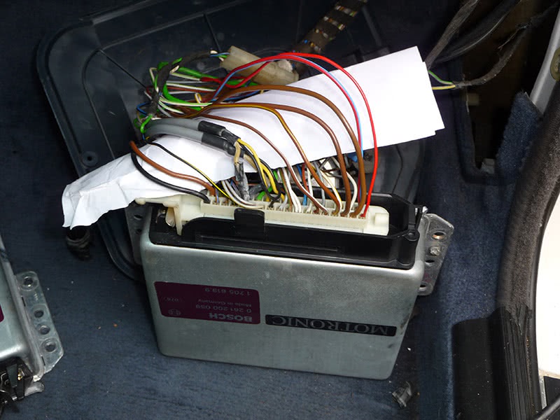
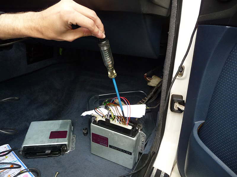
To make things easier, I isolated all the wires I needed to check by locating them within the PCM connector (Figure #4). Before I got too technical and started checking dynamic sensors and driver circuits with a scope, I decided to keep it simple by first checking the PCM powers and grounds with a test light. I wanted to perform a static test to validate whether the PCM was getting what it needed to keep itself alive and breathing with the key on. This is a step very few techs ever bother to do prior to jumping into elaborate testing procedures. The grounds at pins # 5, 10, 16, 17, and 19 all illuminated the test light, but this only validated that there was enough of a ground to operate a 300 mA draw on a testlight bulb, or the under-100 mA draw of a PCM at rest with the key on, engine off. Remember, while cranking, a coil driver within the PCM can draw as much as four to six amps, so the valid dynamic test would be to check voltage drop from the negative side of the battery to all PCM grounds while cranking with the PCM harness connected and using a limit of not more than 300 mV.
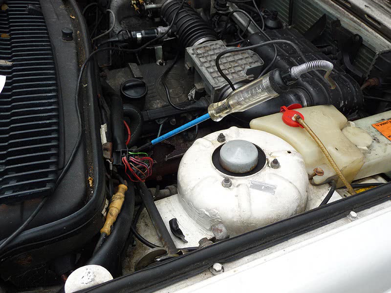
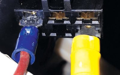
I now moved on to the power feed checks and found that there was battery voltage at pin #18, no illumination of my test light at pin #35 for ignition feed (Figure 5). I had to trace out another part of the wiring diagram to determine what circuit was responsible for sending power to the PCM with the key on (Figure #6). I followed pin #35’s wire on the diagram and it led me to a main PCM relay located in the right rear of the engine compartment. The relay contact got the same battery feed as PCM pin #18, and it illuminated my test light. On the relay coil side there was a good, constant ground, but there was no power (Figure #7).
I temporarily hot-wired the relay coil, cranked the engine, and it started. As soon as I pulled power away from the relay coil, it cut out and wouldn’t re-start. Okay, so now I found the essential problem, but I needed to backtrack some more to see where this power feed came from. The diagram labeled the power feed as coming from a source called “OBC relay box.” I was not familiar with this component, so I had to take a crash course on what this device was all about because I was not you’re a BMW guru, but rather a generalist who learns on the go.
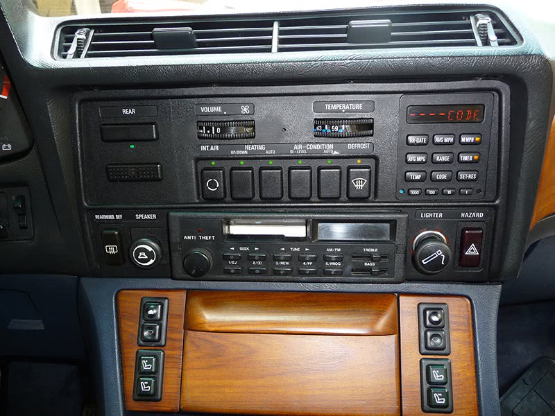
After doing some digging in my information systems, I found that there was an “On Board Controller” in the center of the dashboard. It had a multi-function control panel to the right of the heating and air conditioning panel that displays date, time, miles per gallon, and also allows the driver to enter a programmable four-digit access code to start the car (Figure #8). This was an early security system that disabled the vehicle once activated by the driver through this panel. The system was also designed to default to theft mode if the battery ever went dead, and display the word “CODE” in the panel. Once the battery is restored, the prior access code would no longer be valid and a new code would have to be set up through a series of steps.
The owner tried to enter a new code several times before having the car towed, but it still wouldn’t start. The shop allowed the battery to drain a few times, which caused the OBC panel to go into theft mode. I was successful in programming a new code into the system, but the OBC unit still wouldn’t send ignition feed to the PCM relay coil. I pulled out the OBC device and did some power and ground checks on it, but everything tested okay. I did some further research and what I discovered was that BMW had issues with this panel. So, at this point it came down to the decision of whether to replace the panel, or simply bypass the relay driver coming from the panel and provide a direct ignition feed to the PCM relay coil. The shop alerted the owner of my findings, and he decided to have us bypass the panel to get the car back on the road. He could always decide later if he wanted to spend the money to re-enable the feature.
This was an interesting case that ended with a simple fix. There was no scan tool to hook up to this car, nor a need to use a scope. It just took a basic understanding of what a computer needs before it can operate an engine. It is important prior to testing any onboard controller to power-flow a system diagram so that you become familiar with how its circuits are laid out, and all the components involved. The game plan always starts on paper. Then you home in on the circuits you need to check. Always do this at the PCM because it’s the only way to guarantee that you’re checking all the circuits fully.
by John Anello, “The Auto Tech on Wheels”



0 Comments