
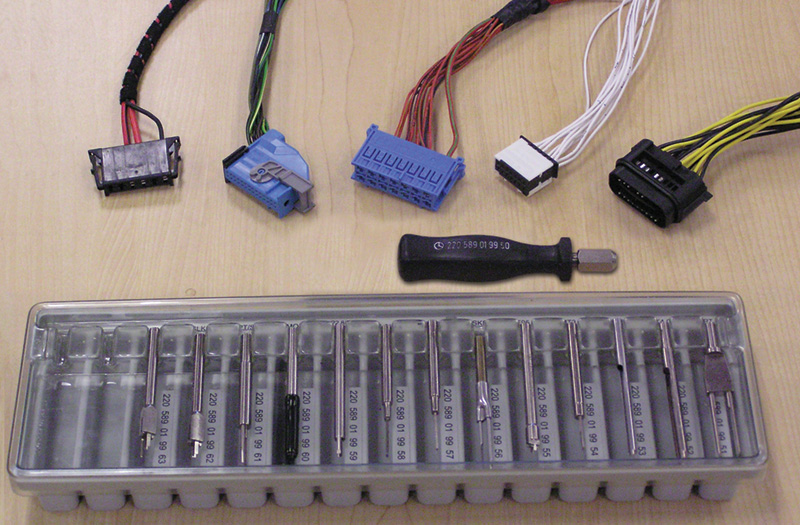
When an electrical fault occurs, the old twist and tape repair is no longer an option for today’s tiny electrical terminals and connectors. Rather than scrambling to find the parts and tools needed when faced with an electrical problem you haven’t seen before, you should be using the Mercedes-Benz Wiring Harness Repair Kit. It contains every type of terminal, connector, and tool needed for wiring harness repairs.
Fifty years ago, the average vehicle contained under 200 feet of electrical wiring. Thanks to an ever-increasing number of electronically-controlled automotive devices, luxury vehicles today may contain up to a mile of wiring. Connecting those wires requires over 1,000 terminals, plus related connectors, seals, and protective housings.
To maintain high Mercedes-Benz performance standards, every wire, terminal, and connector is designed to meet specific application requirements. As a result, you’ll see different wire thicknesses matched to the amount of current a circuit is designed to carry, and contrasting insulation types based on the need for heat shielding and resistance to moisture, abrasion, oil, and chemicals. You’ll face a variety of terminal and connector combinations to meet vibration, shock, and other abuses common to certain automotive locations and environments.
Mercedes-Benz engineers have designed superior wiring connections that provide electrical conductivity in spite of vibration, high heat, moisture and automotive chemicals, and that perform reliably for many years.
But the automotive environment challenges even the best over time. Loose connections, frayed wires, and corroded terminals reduce the flow of electrical current. Improper repairs, inadvertent severing of a line, crushing or cracking a connector, or an animal chewing through insulation all can reduce electrical conductivity. Accidents and severe road shocks can re-position and expose a wire or fitting to moisture, excess heat, or rubbing and chafing damage that is unlikely to have occurred under the original factory wiring layout. Any of these conditions can cause a quiescent current draw, commonly called a parasitic drain.
The wire, or the owner?
Assuming that the charging system is functioning properly and the battery is not dying, before blaming any wiring harness you must rule out improper vehicle shutdown as a cause of battery draw failures. Ignition or lights left on, a door or deck lid not completely closed, or other vehicle system or component consuming power when it should normally remain inactive after engine shutdown can cause a quiescent current draw.
The current path
Once you’ve ruled out operator error as a cause, you’ll need to identify the likely source of the quiescent power draw. Trouble codes and other stored data can help narrow your focus to one or more fuse boxes. A millivolt (mV) drop test across the fuses, or an amp clamp test of various circuits can help pinpoint the circuit where the fault originated. It is no longer accepted practice to use the traditional method of pulling fuses one at a time to find the one with the unwanted draw. That will just confuse the diagnosis by waking up modules when the fuses are plugged back in.
Now you can locate the specific wires and connectors on the wiring diagram, and begin visual inspection and testing to identify the fault-causing damage. The damage will determine what type of repair can best ensure that the problem does not reoccur.
Contact faults
. Insert the axial connector onto the cut end of the wire, narrow end first.")
Select the appropriate Raychem axial solder connector based on the cable cross-section (diameter of wire, including insulation). Insert the axial connector onto the cut end of the wire, narrow end first.
Anything that prevents terminals and connectors from maintaining contact over their mating surface area effectively reduces the conductivity of the connection. Poor conductivity may cause a controller to not see sufficient voltage at a given pin, and shut down operation of that circuit.

Twist the wires neatly and cleanly, then slide the connector over the spliced area.
Cable that is not pushed far enough into the contact portion of a crimped or soldered terminal must be cut off and inserted into a new terminal. Insulation that has been pushed under the wings of a crimp may form stress cracks and eventually allow current to find a new path away from its intended destination. Incorrect, missing, or deformed terminals or pins must be replaced.
Housing/Coupler faults
 to 752° F (400° C). Push the axial connector sleeve back to where the solder pre-form is centered over the twisted together wire. Heat the sleeve from center to ends until the solder melts completely and the sleeve has shrunk properly around both ends of the wires. Pre-heating the gun cuts down the amount of time it takes to melt the solder, thus reducing the risk of overheating the wires.")
Pre-heat a hot air blower/heat gun (with automatic temperature control) to 752° F (400° C). Push the axial connector sleeve back to where the solder pre-form is centered over the twisted together wire. Heat the sleeve from center to ends until the solder melts completely and the sleeve has shrunk properly around both ends of the wires. Pre-heating the gun cuts down the amount of time it takes to melt the solder, thus reducing the risk of overheating the wires.
Loose screw connections must be tightened to the proper torque specification, or replaced if damaged beyond repair.
A cracked or warped housing or coupler casing, in addition to not holding terminals and connectors in close contact, may have the opposite problem. The damaged housing may squeeze terminals too close together, creating potential unintended pathways for current to jump from one circuit to another. Damaged housing components must be replaced.
Wiring faults
 in the same wire, stagger the connectors so that the soldered centers are not directly above each other. To protect against chafing, wrap the finished wire with fabric tape. In the engine compartment, fabric tape should only be used in combination with other (watertight) safety measures.")
When soldering multiple cores (conductors) in the same wire, stagger the connectors so that the soldered centers are not directly above each other. To protect against chafing, wrap the finished wire with fabric tape. In the engine compartment, fabric tape should only be used in combination with other (watertight) safety measures.
Minor abrasion of the wire exterior (insulating tubing) can be covered with new PVC tape. Insulation that has separated from the wire or is cracked, cut, or damaged in a way that would allow current to escape or moisture or other contaminants to directly impact the wire must be cut and repaired.
A missing or damaged grommet increases the risk of a wire rubbing against a sharp edge as it passes through a panel. Fit a new grommet as needed.
Mercedes-Benz wiring harness repair kit
Mercedes-Benz approved wiring harness repair methods include use of Raychem solder connectors (radial, axial, and either type in combination with a cable tail), crimping (round or flat wires), soldering (for solder-type contacts only), and snap-lock rapid connection technology. All of the approved connectors, tools, and die sets are available in basic and extended wiring harness repair kits from Mercedes-Benz. It is explicitly prohibited to use the old fashioned twist and tape method, wire nuts, direct soldering of wires or pins (except to specific solder-type pins), or unapproved crimp connectors.
 between the wire end and the housing is large enough to prevent a short circuit.") Position the end of the wire or cable approximately 2 mm from the edge of the connector housing. This ensures that both sides of the notch grip the wire, and that the gap (a) between the wire end and the housing is large enough to prevent a short circuit. |
 Press the top and base of the cable connector block together using pliers. |
 Select a Rapid Connection Technology cable connector with enough cross-sections to hold each wire in a separate notch. Insert wires or cables into notches in the top half of the cable connector. |
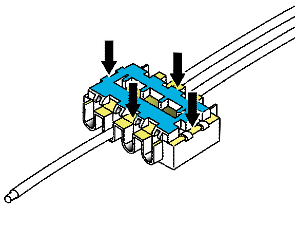 Check that the connector has snapped tight on all four sides. If possible, secure the connector in vehicle to prevent rattles. |
 On the left is a manual crimping tool with the jaws open and contact and wire in position, ready to be crimped. Note that only the small end of the blue seal is inside the crimper jaws. On the right, the crimper has fully closed around the contact and wire. The wide end of the seal remains uncompressed, so it will fit snugly when the contact or terminal is inserted in its connector or housing. |
|

The Mercedes-Benz-approved hand-held crimper for flat cable allows lateral adjustment of the ribbon so that the copper conductors align properly where the cable ends meet. The cable is correctly aligned when light from tiny openings in the tool is fully visible between two conductor tracks.
Raychem solder connector
Soldered connections require tight control of key factors such as soldering temperature, flow and wetting, and the amount of solder deposited on the conductor and terminal. Simple things such as improper tinning of the soldering tip, or excess solder blocking the port for a pin or wiring terminal, can reduce conductivity and weaken repair durability.
 enclosed, but not crushed, gouged, or misshapen by the crimped tab (A2), and tabs clamped properly around the outside insulator (A1). “B” shows the wire stripped too much so that the ears are not gripping the insulation. In “C,” the wire is inserted too far into the connector and sticks out to the tip. If the tabs are piercing or deforming the conductors (B), or insulation (C), a new connector must be installed and the crimp re-done.")
“A” shows a correctly-crimped connection of multi-strand wire with the exposed portion of the wire (A3) enclosed, but not crushed, gouged, or misshapen by the crimped tab (A2), and tabs clamped properly around the outside insulator (A1). “B” shows the wire stripped too much so that the ears are not gripping the insulation. In “C,” the wire is inserted too far into the connector and sticks out to the tip. If the tabs are piercing or deforming the conductors (B), or insulation (C), a new connector must be installed and the crimp re-done.
Mercedes-Benz approves soldering as a repair for small and medium diameter electrical wires, but only using Raychem pre-fabricated solder connectors. These approved connectors help technicians achieve the required control of key soldering performance factors. They reduce repair failures by restricting where the contact parts can be placed, making it easy to see whether the correct length of wire has been stripped and properly positioned for joining, and helping to hold it in position during the solder application.
Several different connectors accommodate various wire outside diameters. Each different solder connector is designed to match a specific combination of wire color code, core (conductor) diameter, and insulation thickness.
, with no gaps (B) inside the crimp and no strands outside (C) of the crimp. If tabs are compressed all the way to the bottom of the connector (D), the crimp is weakened and should be re-done with a new connector.")
A cross section view of a properly crimped wire shows all wire strands fully enclosed by the crimp (A), with no gaps (B) inside the crimp and no strands outside (C) of the crimp. If tabs are compressed all the way to the bottom of the connector (D), the crimp is weakened and should be re-done with a new connector.
Cables 6 mm or larger cannot be repaired and must be replaced. For smaller wires, regular soldering is permitted, but using only the basic radial or axial soldering connectors in the Mercedes-Benz wiring harness repair kit. See the kit instructions and the Mercedes-Benz Workshop Information System (WIS) or other approved repair information source for details on a specific Mercedes-Benz model or component.
If you are removing damage and splicing back together only one wire, the Raychem Axial Solder Connector is the Mercedes-Benz approved repair method. The pre-fabricated sleeve contains a flux-filled pre-formed solder, adhesive-lined end seals, and a polyvinyl heat shrink casing. The translucent sleeve makes it easy to see when melting is complete. It also helps avoid excessive heating, which compromises the dielectric properties of the wire insulation and may result in poor adherence of the solder.
Rapid connection technology
When repairs require you to cut and combine two or more wires simultaneously into a single connector, the Mercedes-Benz procedure requires use of either a Raychem Radial Solder Connector, or for interior (excluding Supplemental Restraint System and other safety-related systems) and trunk wiring only, authorizes use of wiring connectors featuring rapid connection technology.
Rapid connection technology is a snap-lock wire connector block containing tin-plated contacts which touch the wires or cables. There is no soldering, and the lines do not have to be stripped.
Crimping

“A” shows a watertight connection with the wire insulation properly crimped to help prevent moisture ingress and corrosion. In “B,” the seal is not fully engaged by the holding ears, and “C” shows the seal pinched by the ears, allowing a moisture channel.
The first step in crimping is to select the correct crimp contact, or connector. It must match the gauge size and amp rating of the wire, the shape (round or flat), and whether or not it’s required to seal against moisture. Any Mercedes-Benz Wiring Harness repair kit includes a lookup table showing crimp connector options based upon these and other relevant factors.
Strip the wire using an approved Mercedes-Benz wire stripper. The approved tool allows you to strip the wire without fraying or pulling it apart, and cut through the insulation without extra pulling or multiple cuts. That means no nicks or gouges in the wire surface to cause contact gaps or fitting problems that reduce current flow or create an unreliable connection. Avoid unapproved stripping tools.
Select the correct crimping (die) set and mount it to the Mercedes-Benz crimping tool. Insert the crimp contact (connector) into the positioner in the crimping tool. Slide the stripped wire into the connector and ratchet the crimping tool until it is fully closed.
Frustration fighter
The days of finding out the hard way that your screwdriver cannot pull the pin without damaging the contacts, or hoping that there is a comparable connector in good condition in your salvaged parts pile, are finally over. Mercedes-Benz engineers have done a masterful job of collecting everything you need to make wiring harness repairs the safe way, and combining them in one of several different Mercedes-Benz wiring harness repair kits.
Note: diagrams within this article are colored for reference purposes only.


0 Comments