
No interpretation from scan tools or OBD II, just data from “the horse’s mouth” on relays, switches, sensors, circuit voltage drops, etc. We’ve always recommended this before condemning an expensive part.

Scan tools notwithstanding, a professional-grade DMM is still as essential as a soldier’s battle rifle.
Sometimes you have data from a scan tool, but you need to further test and evaluate a part or system that may be causing trouble. Here are some tried-and-true tips for testing individual components.

This DMM can take up to 20A read directly.
Before scan tools
Many technicians working today have only heard about the days before scan tools, and there are some of us who watched the technology boom during our careers. We can remember as young technicians in training being told about the future — for example, some day there would be no more points and condensers for ignition, and, get this, no distributor, either! Some of the older “mechanics” in our classes had a good laugh over that. Back then, electronic ignition was a distinct possibility, but the concept of sorting spark without a distributor seemed like science fiction. The point being that almost everything we tested back then was done individually, and you had to develop the skills to do that. That’s still needed today.

If you want to check fuses or any feed of battery voltage with a test light…
Tools of the trade
Of course, if you have a superior scan tool such as the XENTRY and have put in the time to learn how to use it to best advantage, in most diagnostic situations it makes sense to see what it can tell you as a first step. Sometimes if you’ve already got a good idea about what’s causing the symptoms, however, you can save time by going directly to the likely component or circuit. Also, it’s good practice to verify the scan tool results before you replace an expensive part.
One of our go-to devices for component testing is a classic digital multimeter (DMM). Any high-quality DMM should have measurement functions, troubleshooting features, and dependable accuracy for solving various problems on both conventional and hybrid vehicles. In addition to having all standard multimeter features such as the capability of measuring voltage, current, continuity, and resistance, it should also be able to perform diode tests and pulse width measurements in milliseconds for fuel injectors, etc., both of which come in handy. Other common functions include rpm with a suitable pick-up, and temperature with an optional probe.
A professional-grade DMM can take current measurements up to 20A for 30 seconds and 10A continuously. A magnetic hanger will let you attach the meter to most steel surfaces for easy set-up and viewing. Some are also designed to be used in high-energy environments as found in hybrids.

…always use the LED type as the old-fashioned incandescent-bulb variety can draw enough current to damage electronics.
Other equipment that’s useful for individual component testing includes:
- Just as in the old days, nothing’s handier or faster than a 12V test light. Remember, you MUST use only the LED type on modern vehicles as the obsolete incandescent bulb variety can draw enough current to damage sensitive electronics.
- Connected to the vehicle’s battery, a power probe can easily activate electrical components, detect circuit polarity and continuity, and test wires for bad ground connections and resistive power feeds.
-

A low-amp inductive probe that works with your DMM or lab scope allows you to read small currents without breaking connections.
Automotive lab scopes are available in a wide range of prices from very expensive to quite affordable. These are really helpful when confirming patterns of crankshaft and camshaft position sensors, fuel injector waveforms, and ignition coil patterns. Having a low-amp probe to go with it is very helpful in checking current ramping.
You’ve verified the concern, now test the part!
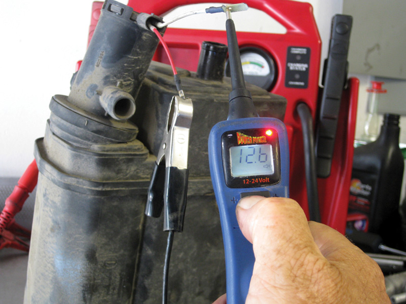
A good way to check an evap solenoid valve is by injecting 12V to see if it works.
We’ll start with solenoids. Some of the most common ones you’ll find in your troubleshooting career is a purge canister or vapor canister solenoid, sometimes called a vent valve. Any solenoid is basically an electromagnet that operates a switch, valve, lock, etc. when its circuit is completed. It consists of a coil of wire and a movable iron core called the armature. When current flows through a wire, a magnetic field is set up around the wire. If we make a coil of many turns of wire, this magnetic field becomes many times stronger. When the coil is energized, the core moves to increase the flux linkage by closing the air gap between the cores. The movable core is usually spring-loaded to retract it when the current is switched off.
In the case of a solenoid valve, there are two types you may encounter: those that are normally closed and those that are normally open (not to be confused with the duty-cycle type). One method of testing is to use the scan tool if possible and energize the circuit. This will allow you to check the circuit to the solenoid for faults. With your voltmeter attached, you should see battery voltage when the energization occurs. You should also be able to hear a click, although that’s not always reliable.
Although we’ve seen service manuals refer to testing by using your DMM’s ohms function, and give specifications for resistance, it has been our experience that this method is somewhat unreliable. We prefer to actually apply battery voltage and ground using a power probe or other method and watch/listen for the solenoid to operate. By applying vacuum with a manual pump, you can see if the valve is operating as designed. In a pulse width modulation (PWM) solenoid, a DC supply voltage is switched on and off at a given frequency for a modulated period of time (duty cycle). The duty cycle is the “on” time of the voltage and is expressed as a percentage of the time period. At 50% duty cycle, the voltage is “on” for 50% of the time, and “off” for the remaining 50%. Therefore, the time-averaged voltage is only 50% of the maximum supply voltage, and the current to the solenoid is only 50% of maximum current as well. It is this time averaging that allows PWM signals to be used for proportionally controlling solenoids.
A lab scope can be helpful here. You should have a known-good pattern to go by — usually available in the repair procedure in XENTRY.
Pushing gasoline

Excessive oscillations of the brushes can cause their leads to break from fatigue. If the springs are grounded, they will complete the circuit, but not for long.
So, you suspect a worn out fuel pump. Your pressure and flow tests have revealed a problem with the internals of the pump and now you need to confirm your suspicions. Being able to energize the circuit with the scan tool is helpful, but you can use other methods. If the pump runs, but you are concerned about poor performance in the form of low psi or flow, then you need to do some testing. Check for available voltage at the fuel pump as close as possible to the pump itself. Really important here is to check for voltage drop. Wires carrying current always have inherent resistance to current flow. Voltage drop is defined as the amount of voltage loss that occurs through all or part of a circuit due to resistance. To check for voltage drop in a circuit, connect your voltmeter’s test leads in this manner: positive lead to the battery positive post and negative lead to the current supply lug of the device being tested — in this case, the fuel pump. Then the circuit must be energized (pump turned on) to get a reading. The traditional rule of thumb was 0.2V drop per connection as allowable, but with today’s sensitive systems anything more than 0.1V is cause for concern. Realistically, however, you should never see more than .5V drop or the pump will be starving for voltage.

This is the kind of reading you should like to see when checking voltage drop in the pump’s ground.
Check all the connections until you’ve found the culprit. Be sure to test the ground side of the circuit as well. Simply connect the ground lead of the DMM to the negative post of the battery and the positive lead to the ground circuit, again as close to the pump as possible. Another great test of the pump is to use your lab scope and a low-amp probe to check the current ramp pattern.
What is current ramping? Basically, fuel pumps are electric motors, and electric motors work by flowing an electric current to the coil windings through a set of carbon contacts (brushes). The windings have a set of contact points called commutators. As the coil windings rotate, the carbon contacts make a different set of connections, which show up on the current waveform. By analyzing this waveform, you can deduce a couple of details about a fuel pump motor. First, a determination has to be made as to the number of commutators involved. This is easier said than done, but for now it is important to know that most pumps have eight commutators. Given this information, it is possible to determine the speed of the motor, and, by doing so, the condition of the fuel pump. By simply freezing the waveform and measuring the time it takes to make eight current “humps” (eight commutators), all we have to do is divide 60, 000 by such figure — it takes 60 seconds to a minute and 1,000 milliseconds to a second, so 60 sec. x 1,000 ms = 60,000 ms. This can actually be applied to any electric motor. By knowing the rotational speed and current draw of a fuel pump motor, we can determine its condition.

Note that in this fuel pump test the rpm is fast and the amperage draw is low.
A faster-than-normal fuel pump, with low current draw, points to a lack of resistance in the fuel flow. A defective fuel pressure regulator letting too much fuel return back to the tank, a worn-out impeller, a clogged suction filter sock, etc. can all lead to a fast-spinning pump. The same even applies to a returnless fuel system as it still has an internal fuel pressure regulator. On the other hand, a slow pump with high current draw points to a restriction in the fuel lines. A clogged fuel filter, restricted fuel pressure regulator, etc. will slow the rpm of the armature since it has to push the fuel harder. Your lab scope will also give you average current draw in amps as well to help in your troubleshooting.
Relays

Since Mercedes-Benz vehicles last longer than other makes, you might still be seeing the KLIMA relay in your shop. While it’s more complex than a basic relay, it can still be tested directly.
A relay is an electromagnetic switch operated by a relatively small electric current that can turn on or off a much larger electric current. This consists of an electromagnet (a coil of wire that becomes a temporary magnet when electricity flows through it), sometime called a field coil. You can think of a relay as a kind of electric lever: switch it on with a tiny current and it switches on (“leverages”) another device using a much bigger current. Why is that useful? As their name suggests, many sensors are incredibly sensitive pieces of electronic equipment and produce or modify only small electric currents. But often we need them to drive larger components (pumps, motors, etc.) that use bigger currents. Relays bridge the gap, making it possible for small currents to activate larger ones. That means relays can work either as switches (turning things on and off), or as amplifiers (converting small currents into larger ones).
For illustration purposes, we’ll look at the common Bosch four- or five-pin relay used on many Mercedes-Benz automobiles. The pins will be labeled 85, 86, 87, 87a, and 30. Most relays will have similar configurations. Pin 30 is connected to a fused 12V feed. Pin 87 is “load,” the device to be operated. Number 85 is negative for the coil, and 86 is positive for the coil. Relays can either be positive-side-controlled or negative-side-controlled. When voltage is applied to pin 86 and pin 85 is grounded, the field coil is energized and the switch is pulled in, sending the line voltage from pin 30 to the load-side pin 87 (normally open or off). Pin 87a is used where you want to have a normally-on circuit. Your power probe is a great tool for applying voltage or ground to the field coils. Then you can check for current flow through the relay with your voltmeter.
Position sensors
Checking the signal on a typical camshaft or crankshaft position sensor is relatively simple. If your diagnostics lead you to suspect a fault here, it’s time to get out the lab scope. After consulting the manual for a known-good waveform, attach your scope’s test lead across the signal wire of the sensor and a good ground.
There are two types of revolution or position sensors you will encounter in your testing:
-

A typical variable reluctance sensor.
Variable Reluctance Sensor.
This consists of a pickup coil, a magnetic core, and a permanent magnet, and is mounted next to a gear wheel or reluctor. As the teeth of the gear wheel pass by the face of the magnet, the amount of magnetic flux passing through the magnet, and consequently the coil, varies. When the gear tooth is close to the sensor, the flux is at a maximum. When the tooth is farther away, the flux drops off. The moving target results in a time-varying flux that induces a proportional voltage in the coil, which varies as a function of the speed rotation and the distance to the gap in both frequency and amplitude. The typical waveform of this type can be seen in Figure A. Look for dropouts and glitches for intermittent problems.
Figure A. A known-good camshaft position sensor’s waveform.
-

Figure B. A Hall Effect waveform.
Hall Effect.
This consists of a semiconductor sensor combined with an electronic circuit that protects the sensor from possible voltage peaks, and a permanent magnet. The operating principle is based on the Hall Effect, a phenomenon in which voltage is generated by the action of a magnetic field acting at a right angle on a thin conducting material. The waveform we get from the sensor is a “U” wave as opposed to the sine wave in variable reluctance sensors. A typical waveform can be seen in Figure B.
Fuel injectors and oxygen sensors
Fuel injectors can be electrically tested using your multimeter’s voltage function combined with the ms function (CAUTION: Late-model piezo fuel injectors must not be tested with a voltmeter as they are very sensitive to electrical connections).

There are better ways to test a traditional heated oxygen sensor, but the heater itself will reveal its condition through the use of a DMM.
With a traditional heated oxygen sensors (as opposed to an AFR, or Air/Fuel Ratio sensor), most of the time you will be able to see the waveform through your scan tool, but a common failure code will be for the sensor heater circuit. In this case, you will want to use your ohmmeter function to test this circuit. Look up the resistance specification, and connect the meter to the leads according to the diagram. Most of the time, a faulty heater will be open.
Being thorough pays off
In most cases your diagnosis of a faulty part will begin with a scan of all vehicle systems. But when your diagnostic platform directs you to a possible faulty part it will pay off very well indeed to do your homework and be thorough in individual component testing. It will give you peace of mind knowing you’ve done due diligence, as well as pay you back for your equipment investment.


0 Comments