
Does the fan come on at odd times, maybe not at all, or runs continuously? Here’s an overview of the functionality of engine cooling fans and their circuitry.

Here’s an older design of a dual electric fan system on a 140 model.
Engine cooling fans have been in operation on most production cars for well over a century. Circulation of water or coolant through a heat exchanger (radiator) has been the traditional method of keeping waste heat from destroying the engine. When the vehicle is at cruising speed, there is enough air flow through the fins of the radiator to facilitate the proper exchange of heat. When the vehicle is idling or moving slowly through traffic, however, there’s a crucial need to move additional air through the cooling fins. Hence the introduction of the cooling fan.
Early models simply had a fan with two or more blades attached to a drive pulley, often on the water pump shaft. As vehicle design became more concerned with maximizing power and efficiency, engineers saw this as an area of wasted energy. The first attempts at mitigating this waste was the introduction of the fan clutch, a thermostatic engine cooling fan that can freewheel at low temperatures when cooling is not needed, allowing the engine to warm up faster, and relieving unnecessary load on the engine. As temperatures increase, the clutch engages so that the fan is driven by engine power and moves air to cool the engine. Most fan clutches are viscous or fluid couplings, coupled with a bi-metallic sensor system similar to that in a thermostat. These are still in use today.

The electronically-controlled fan clutch went a long way in increasing efficiency and keeping the fan from spinning when it’s not needed.
Some attempts to further enhance the efficiency of the fan included electronic controls, which regulate the level of engagement depending on any number of inputs. Common controlling factors might include engine oil temperature, transmission oil temperature, coolant temperature, A/C system pressures, and ambient air temperature.
As automobiles added air conditioning and other accessories the need for more efficient engine cooling became evident. Enter the electric cooling fan.
Early electric cooling fans
The addition of air conditioning was probably the most influential factor in the need to engineer a better method of moving air through the radiator. The addition of the condenser restricted the air flow somewhat in addition to heating the flow. These took the form of one or more fans mounted in front of the radiator and condenser that “push” more air through the two units.
The earliest designs had fairly simple circuitry controlling the fans. Engine cooling fans are big consumers of electricity, so there’s always been a need for some special considerations in circuit design. How much current do they draw? There are a lot of factors that determine this, and the amount of amperage the motor requires is only one of them. Amperage and airflow are related, but you must also consider the pitch of the fan blades, the diameter of the fan, the shape of the fan shroud, and also what it is that you are trying to move the air through. For example, is the fan trying to move air through an oil cooler that is only 3/4-inch thick, or is it trying to pull the air through a five-core radiator that has an air conditioning condenser and charge-air-cooler stacked in front of it? All manufacturers rate their fans by cubic feet per minute (CFM) of airflow at zero inches static pressure. This is the amount of air the fan moves without anything in front of it. A typical two-core radiator will create about 0.5 inches of static pressure in front of the fan. The factors that determine the CFM rating of a fan are the motor itself, the fan speed (rpm), fan-blade design pitch, number of blades, diameter, area and design of the fan shroud it is built into, and static pressure.
Amperage
Amperage normally measures how much load an electrical device draws when in operation. Automotive fans are rated at 13.5 volts, and the rating is after the motor is at operating rpm. The initial startup of the fan will have an amperage spike of up to 60%, which lasts only a millisecond.
Compare the factors that shape the CFM rating of a fan to these items that affect the amperage draw of an electric fan motor: efficiency of the motor, weight of the fan blades, resistance of the electrical components, mechanical resistance of fan rotation (bearings and bearing tolerances), and the amount of airflow (CFM) through the fan. That said, in typical automotive installations you will see anywhere from 15-amp to up 60-amp draws in fan motors. You’ll need a heavy gauge wire to drive the fan, and to switch it on you have to have a relay in the circuit unless you want to put in a switch the size of the one in your living room wall that controls the lights.
From this simple circuitry, we have evolved into more and more complex fan controls. In the 140 model and similar systems, the auxiliary fans are switched on with infinite speed adjustment depending on the refrigerant pressure and or/coolant temperature. The pushbutton control module receives coolant temperature data from the A\C coolant temperature sensor and the refrigerant pressure from the refrigerant pressure sensor. This input information is transferred to the auxiliary fan control module by the pushbutton control module. The auxiliary fan control module processes this information and compares it with stored values. The resulting request is then transferred to the auxiliary fan.
Newer systems
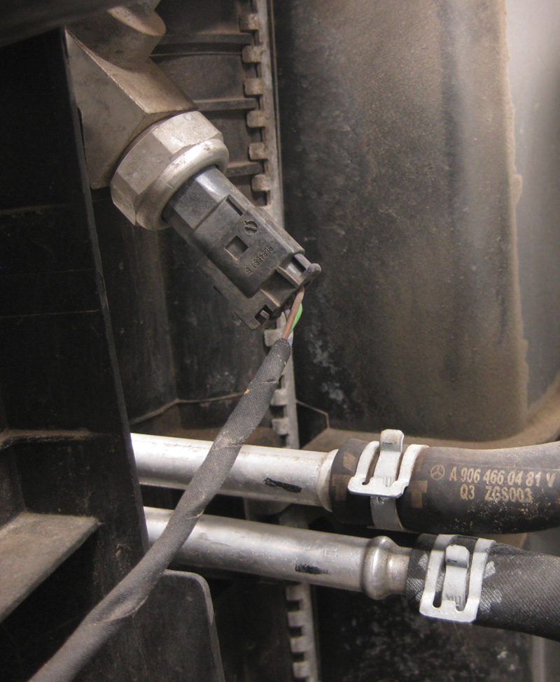
The refrigerant pressure sensor is usually located between the compressor and the condenser.
With the introduction of the W211 and similar models, a more complex system was designed, which requires more detailed diagnostic procedures as well as a strong understanding of system operation . Any attempt to provide the details of all the cooling fan circuits found in Mercedes-Benz automobiles would require volumes of writing. For the sake of brevity, we will describe some of the basic systems you’ll find on most of the vehicles you service. It is most important to note that in attempting to solve any cooling fan faults, you should have access to the factory workshop manual wiring diagram (think StarTekInfo and WIS). Trying to solve any faults without a thorough knowledge of how the system was designed to operate will be futile at best.
Here are some details of the individual components involved:
- Refrigerant pressure sensor – the pressure measured by the refrigerant pressure sensor is compared with a value stored in the pushbutton control module. When the following values are present the fan is adjusted infinitely:
- Refrigerant pressure > 16 bar = fan low speed
- Refrigerant pressure > 20 bar = fan maximum speed
- Pushbutton control module – controls the AIR (fan) control module with a minimum of 3mA and a maximum of 10mA. The fan control module compares these with stored values and switches on the auxiliary fan under the following conditions:
- Outdoor temperature > 5 C
- Refrigerant pressure ≥ 13 bar
- Coolant temperature ≥ 103 C

Be sure to check for corrosion on connectors.
With complaints of a cooling fan that runs continuously, the workflow would be something like this:
- Check all fuses. Inspect connections on the Engine Coolant Temperature (ECT) sensor and the A/C pressure sensor on the receiver-dryer. Pay particular attention to corrosion on the connectors as extra resistance can cause faults.
- Connect a Mercedes-Benz fully-functional and compatible scan tool to retrieve/record/clear DTCs in the Engine Control Module (ECM), Signal/Activation Module (SAM), Automatic Air Conditioning (AAC), and Instrument Cluster Module (ICM).
- Attempt to access the activations menu in the scan tool under the PCM. Use the scan tool to activate and control the engine cooling fan. If the fan is not controlled, check voltage signals at the Fan Control Module (FCM) (N76) located under the left front headlight behind the bumper. Check your workshop manual for locations on other models.
- Use a Digital Multimeter (DMM) for voltage testing at the connector on N76. Pin 3 Red/Black (RD/BK) should be battery voltage (B+) at all times. Pin 6 Black/Red (BK/RD) should be B+ with the key in the “On” position (#2). Pin 2 Brown (BN) should be constant ground. Pin 5 Yellow/Blue (YE/BL) should be the control signal from the PCM. Depending on the control signal from the PCM, the voltage will vary between 2V (low speed) and 11V (high speed). If voltage is high (above 10V all the time), open the connector to eliminate the possibility of feedback voltage from the N76 module and recheck command voltage on pin 5.
- Check the version-coding of the Electronic Ignition Switch control module (EIS), the left front Signal Activation Module (SAM), the PCM, and the Climate Control Pushbutton Control Unit. Newer versions are introduced from time to time and may be necessary for completing the repair process.
Some cooling fan complaints may not be caused by a faulty part at all, but have been remedied by a software update as in the case of models with ME97 or ME97 AMG control units. It is very important to check TSBs for any updates. For example:
- 2237 Coolant temperature sensor 1 has a malfunction. The fault can occur at high-temperature differentials (outside temperature/coolant temperature), as may occur after driving out of an air-conditioned garage into high ambient temperatures.
- Cause: High temperature differences can lead to this DTC being set in the ME control unit. This DTC is set due to the programed temperature limit data in the ME9.7 engine control unit.
- Remedy: If a customer complaint exists, please reflash the ME control unit. Vehicles from MY2012 should be flashed using add-on 4067 (XENTRY release 09/2014). Vehicles up to MY2012 should be flashed using 09/2014 XENTRY release (no add-on necessary).
Here is another possible scenario:
- Complaint: Radiator fan starts up without obvious cause although the ignition has been off for longer than 30 minutes. Radiator fan changes to limp-home mode (100% output) while driving, with display message (cooling system) in instrument cluster. Battery discharged.
- Cause: The electric radiator fan may start up by itself with ignition “Off” due to moisture ingress.
- In “Behavior of no-load current” menu, read out the five stored data records. If at least one of the data records contains a no-load current entry of >10A, and if the kilometer reading stated there agrees with the actual kilometer reading at which the vehicle battery was discharged, the radiator fan may have been the cause of the fault.
It is important to note at this juncture that you may have received the following complaint:
- Complaint: Electric radiator fan runs, stays on for too long after ignition is switched off.
- Cause: A delayed fan switch-off after ignition is turned off is dependent on many factors.
- Engine coolant and transmission oil temperature.
- A/C demand and pressure in A/C system.
- In vehicles with a diesel particulate filter, after an aborted regeneration of the DPF, even if the engine is not yet at operating temperature.
During run-on, the fan runs at two speeds — up to a maximum of 50% of the fan speed, the radiator fan may run on for up to six minutes. If another fan is starting up and circuit 15 is switched on, the radiator fan may intentionally be in limp-home mode. If the coolant temperature signal is absent, the engine control unit actuates the radiator fan at maximum speed. If a PWM signal line is defective, the radiator fan likewise switches to limp-home mode.
- Remedy: The radiator fan run-on is intentional. Do not replace any components. This is a normal programming design and you will need to be able to educate the customer to that effect.

A typical later-model cooling fan and integrated suction fan control module.
If the radiator fan is in limp-home mode due to defective actuation lines or pins in the connectors, a fault code is logged in the control unit (codes vary according to model series). In these cases, the wiring harness must be repaired.
In 164 models and later, the ME-SFI or CDI control units (depending on which engine configuration you’re working on) indirectly actuate the fan through the engine or A/C electric suction fan control unit. The fan specified speed is transmitted by the ME control unit to the engine and/or A/C electric suction fan control unit by means of a pulse-width-modulated signal. The on/off ratio is 10 to 90%, which translates to the following:
- 10% electric suction fan OFF
- 20% electric suction fan ON, minimum speed
- 90% electric suction fan ON, maximum speed

Here’s a typical pattern for a known-good pulse-width-modulated signal.
The status of the air conditioning or automatic air conditioning is transmitted from the instrument cluster via the CAN to the ME. The fan specified speed is dependent on this status. The engine and A/C electric suction fan with integrated control (M4/7) is located behind the radiator on most models, but consult your workshop manual.
The fan (fans) are powered by the red-fused (in this case 100A) wire, which is hot at all times, and also a pink wire, which is fused and energized when engine circuit relay 87 is on (ignition on). Ground on the suction fan control unit is a brown wire and typically secured at the right front wheel well. Be sure to do a voltage drop test on this for possible faults when diagnosing fan complaints. The final wire is the control wire from the engine control unit to the suction fan control unit, which sets the fan speed. This is the pulse-width-modulated signal we spoke of earlier. This line is best tested by using a lab scope.
Knowing the system you are working on will be your best asset in diagnosing cooling fan and cooling fan circuit problems for your customers. Consult the workshop manual and wiring diagrams available through StarTekInfo.com or other sources. A thorough inspection of the mechanical components of the system should be part of your diagnostic workflow. What is the condition of the fan itself — are the fan blades okay? Check for cracks and other signs of fatigue and stress. Look at the fan shroud, and check for obstructions, dirt, etc. Lastly, be sure to inspect all of the related harnesses and connectors for signs of damage from chafing, oil or water intrusion, and rodent damage.
Download PDF 〉


0 Comments