

HISTORY, FUNCTION, DIAGNOSIS AND REPAIRS
Volvo started using an electronically controlled rear differential on all their all wheel drive models in 2003 with the adoption of the second generation of the Haldex system on the XC70 and XC90 models. Before that they used a viscous coupler type of rear end with a series of plates bathed in a special type of synthetic hydraulic fluid.
After the early all wheel drive systems were on the road for a while, Volvo realized they could do better, so they started using an electronically controlled rear differential, that was driven with an electric pump controlled by the car’s Control Area Network (CAN).
Every year these systems get better and better with a lot more control and improved safety on and off the road. If you want to see how these systems really work and you have an opportunity you can hook up a laptop equipped with Volvo’s VIDA and, under the vehicle communication tab, select DEM and select 10 data pids to monitor. Then have someone else drive the car down an icy road and watch the magic.
Of course it’s best to do this test with the written permission of the owner of the car or your own Volvo, for obvious reasons.
Over the years Volvo has used updated versions of the Haldex rear end, with each new version having more responsive traction control features. Depending on the year and model of the Volvo you’re working on it may have an older or newer version of the Haldex system.
Here are a few examples:
- S60R AWD (Second Gen Haldex 2004-2005, Third Gen Haldex 2006-2007)
- Volvo XC60 AWD (Fourth Gen)
- Volvo XC90 AWD (Third Gen 2008-2009, Fourth Gen 2010-2012, Fifth Gen 2013 – )
- Volvo V70R AWD (Second Gen 2004-2005, Third Gen 2006-2007)
- Volvo XC70 (Second Gen 2003-2005, Third Gen 2006+)
- Volvo S80 AWD
- Volvo XC90 AWD (Second Gen up to 2005, Third Gen 2006-)
Here are some of the features of the different versions of the Haldex systems used by Volvo and others over the years.
PRE-HALDEX VISCOUS COULPLER
Volvo uses Haldex’s AWD system for nearly all of their models since the introduction of their FWD/AWD platform. However, before the switch over to the Haldex system in 2003, Volvo used a viscous coupling to transfer torque to the rear axles. A viscous coupling is an assembly of closely spaced plates bathed in a dilatant type fluid – a lot like the fluid used in the old radiator fan clutches. This viscous coupling links the front and rear drivetrains.
When the vehicle is traveling with relatively equal traction on the front and rear axles, the two halves of the coupler will be rotating at nearly the same speed. When the car loses traction and the front wheels begin to spin, the side of the coupler attached to the front axles will begin to spin faster than the side attached to the rear axles. This difference in speed causes a shearing effect on the dilatant fluid that the coupling is immersed in. However, in practice these early AWD systems did not go far enough in providing traction for all driving conditions. The engineers at Volvo and Haldex knew these systems could do better and over the years developed systems that could handle almost any condition the average driver could throw at them.
HALDEX FIRST GENERATION
The first generation Haldex AWD system is the first reactive hydraulic AWD system produced by Haldex Traction. This means the AWD system relies on wheel slip to activate the torque transfer from front to rear wheels. It uses a mechanical pump connected to the input and output shafts of the Haldex clutch assembly. Normal driving with ample traction means the car is nearly entirely front wheel drive.
When wheel slip occurs, the difference in rotational speed between the input and output shafts drives the hydraulic pump. Operation of the clutch pack is almost entirely mechanical – a mechanically driven pump and a mechanical linear throttle valve were used to determine wheel slip and lockup of the clutch pack, converting the system from 90 percent front/10 percent rear torque distribution to 50/50 torque distribution within 90 degrees of wheel slip.
HALDEX SECOND GENERATION
Haldex second generation is also a reactive AWD system. Second generation Haldex AWD is different from first generation systems with the addition of computer-controlled solenoids to control the clutch plates. This system reacts within 90 degrees of wheel slip. When wheel slip occurs, the difference in rotational speed from front to rear axles activates a mechanically driven hydraulic pump. The pump forces hydraulic fluid through a computer-controlled solenoid, which then engages a set of clutch plates to transfer torque to the rear axles.
HALDEX THIRD GENERATION
The chief complaint about performance on the first and second generation systems was the reaction time required to trigger the torque transfer to the rear axles. Haldex third generation is the first proactive AWD system by Volvo. As soon as the engine is started, an electric pump pre-pressurizes the AWD transfer clutch. When the traction control computer senses wheel slip, the pre-pressurized clutch pack is engaged instantaneously and torque is transferred to the rear axles.
Once engine torque is transmitted through the Haldex unit, the mechanical oil pump takes over from the electric pump and continues to supply pressure to the hydraulic clutch pack. Haldex claims a reaction time of 15 degrees of wheel slip. This AWD system is marketed as “Instant Traction” by Volvo.
HALDEX FOuRTH GENERATION
Haldex fourth generation is virtually identical to the third generation system, but does away with the mechanical hydraulic pump. Instead of relying on the electronic pump to just pre-charge the AWD system, the fourth iteration of Haldex’s AWD coupler uses the electric pump to supply hydraulic pressure for the entire operation of the torque transfer from the front to rear axles. Haldex fourth generation is also a “proactive” AWD system. Volvo continues to market the fourth generation system as “Instant Traction.”
HALDEX FIFTH GENERATION
The fifth generation of Haldex’s AWD system focused on tighter integration of components and simplified construction. Previous versions of Haldex’s AWD system used a set of pumps (mechanical and electronic), accumulators, and solenoids to precisely control hydraulic pressure applied to the clutch pack. The fifth generation system simplified the design and uses only a computer-controlled high pressure hydraulic pump to replace the accumulators and solenoids used in previous versions. Volvo also markets the fifth generation system as “Instant Traction.” The typical problems you will encounter with the Volvo DEM are electrical, but in rare cases you will have a Volvo come into your shop with a mechanical problem in the rear differential.
When a customer comes into the shop with one of these Volvo XC series cars they won’t always have four wheel drive; in a lot of cases they won’t even realize they have no all wheel drive unless they have recently driven in snow or other slippery conditions. The DEM will disengage if it registers a fault to try to protect itself from further damage. And in most cases there will be no check engine light or traction control message on.
The most common DEM fault, seen in most Volvo shops, tends to be problems with the oil temperature sensor in the DEM control module.
VOLVO REAR DIFF SERVICE
Volvo’s recommended service interval for rear differential fluid replacement varies from model to model and year to year, so check VIDA or your service information website for the specific service information you need for the Volvo you are working on. Volvo TJ16773 includes information on the correct Volvo fluid to use.
Of course it’s difficult to know if the Volvo you are you working on has ever had its rear differential fluid changed, and in many cases you will find it has never been serviced.
As a rule of thumb, it’s a good idea to change the rear diff fluid about every 3 years or 30K miles, more often if the customer uses the car for a lot of off road driving or uses the car for towing.
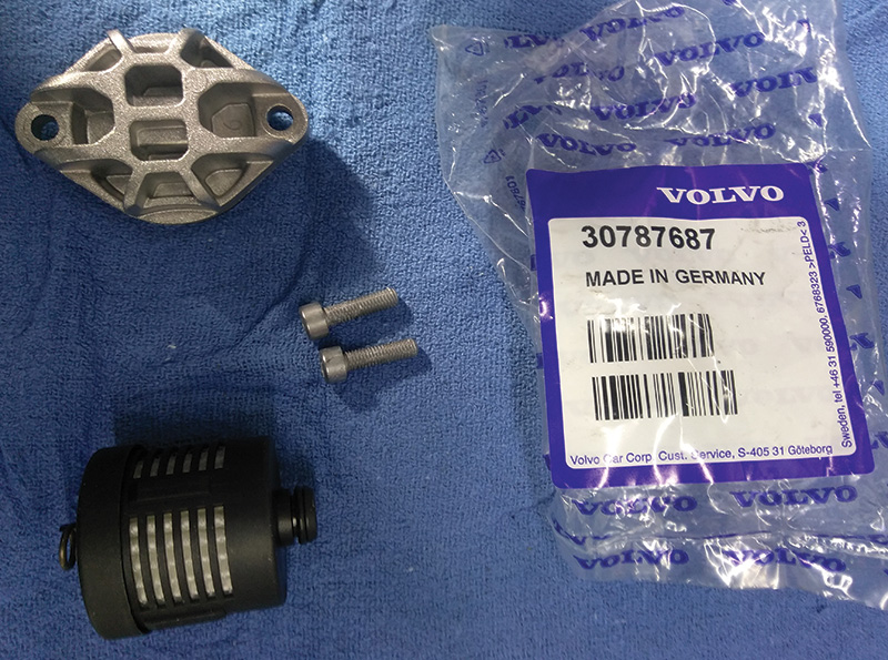
But if you have a Volvo that has high mileage or a Volvo that is having problems with the rear differential, you should replace the Haldex’s filter screen along with new fluid.
Volvo offers a filter kit for earlier models that comes with a new o-ring and an updated filter cover and new bolts.
Gen five Haldex units used in the latest Volvos don’t have a replaceable filter, just a screen on the pump inlet.
REPLACING THE AOC CLUTCH FILTER
Note! As the illustrations in this service information are used for different model years and/or models, some variation may occur. However, the essential information is always correct.
Removal
Caution! The oil filter must be replaced every four years. In the service schedule this corresponds to a normal mileage of 50K miles. However it is the period of four years that is the key factor, not the mileage.
Removing the oil filter
Note! Thoroughly clean around the oil pump before beginning removal.
- Position a container underneath the Active on Demand Coupling.
- Remove the two screws from the cover for the oil filter.
- Remove the loose o-ring furthest into the filter seat.
Installation
Installing the oil filter
- Clean the filter area thoroughly. There must not be any lint from any paper or cloths.
- Position a new o-ring furthest into the seat for the filter.
- Install the new o-rings on the cover. Lubricate the o-rings with a little Active on Demand Coupling oil, P/N 116 1641 (1 liter packs).
- Install the filter and the cover. Tighten to 5.5 N-m.
To fill and check the oil in the Active on Demand Coupling, see Active on Demand Coupling (AOC).
COMMON HALDEX REPAIR PROCEDURE FOR REPLACING (AOC) OIL PUMP
Oil pump Active on Demand Coupling (AOC), replacement
Note! As the illustrations in this service information are used for different model years and/or models, some variation may occur. However, the essential information is always correct.
Preparatory work
Remove:
The rear section of the exhaust system and the propeller shaft from the flange for the Active on Demand Coupling, the flange from the Active on Demand Coupling, and the pinion seal coupling.
Removal
Removing the oil pump
Note! Thoroughly clean around the oil pump before beginning removal.
- Position a container underneath the Active on Demand Coupling.
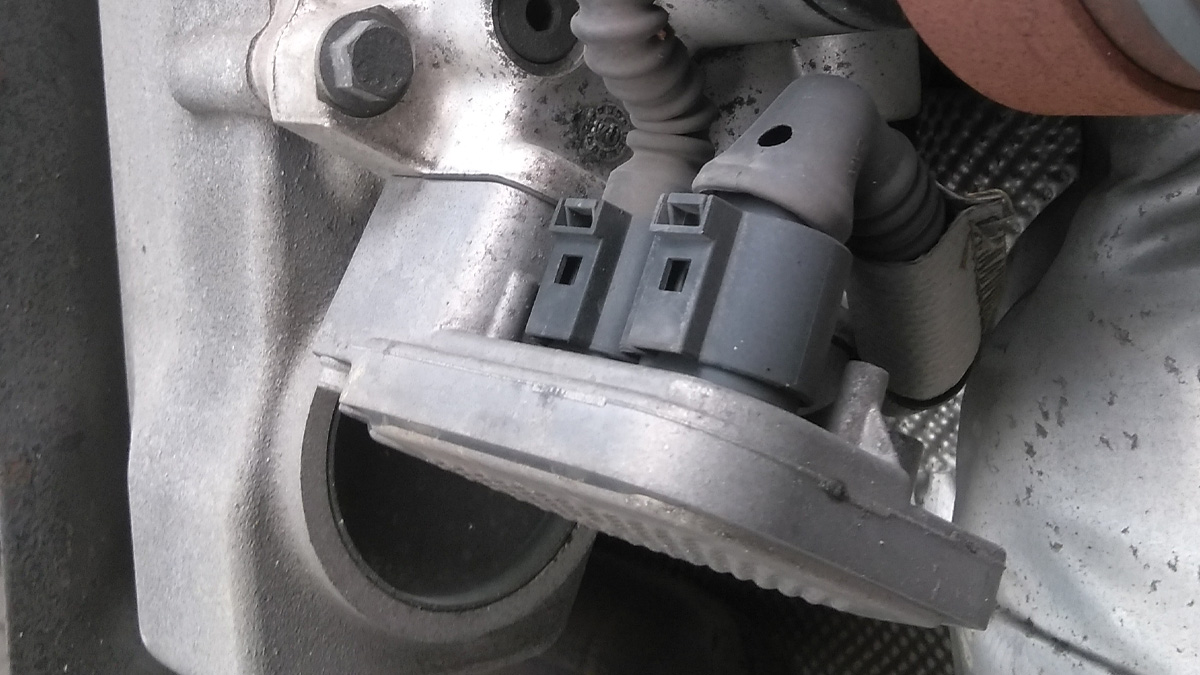
- Disconnect the connector for the oil pump. Remove the tie strap.
- Remove the bracket and the connector for the (DEM) control module. Be gentle with the connector clips because you don’t want to send one of these cars down the road with a loose connector because the (DEM) is always exposed to the elements.
- Remove the two screws for the oil pump. Pull the pump straight out of the coupling.
Note! Later versions of the oil pump have the socket for the cable harness on the side of the oil pump housing. The cable harness is shorter. This version supersedes all previous versions, including as a replacement part.
Installation
Installing the oil pump
- Check that the seat for the oil pump is clean. There must not be any lint from paper or cloths.
- Check that the new o-rings are in position. Lubricate the o-rings
using oil for the Active on Demand Coupling, P/N 116 1641 (1 liter container). - Install the oil pump. Press the pump in as far as possible. Lightly tighten the two M5 screws alternately. Tighten. See the relevant specifications.
- Connect the connector.
Finishing
Fill the AOC (Active on Demand Coupling) with oil. Check the oil level. Install the propeller shaft and the exhaust system.
Note! Later versions of the oil pump have the socket for the cable harness on the side of the oil pump housing. The cable harness is shorter. This version supersedes all previous versions, including as a replacement part.
DEM SOFTWARE AND TESTING
The following DEM DTCs could be caused by a faulty Temperature/Pressure sensor in the AOC (Active on Demand Coupling) on the vehicles listed above: P093211, P093215, P093711, P093715, P093827, P096162, P188973, P188974, P188A68, 0001, 0002, 0007, 000B, 000B.
Service:
Check if the Temperature/Pressure sensor indicates a malfunction by using the procedure described below.
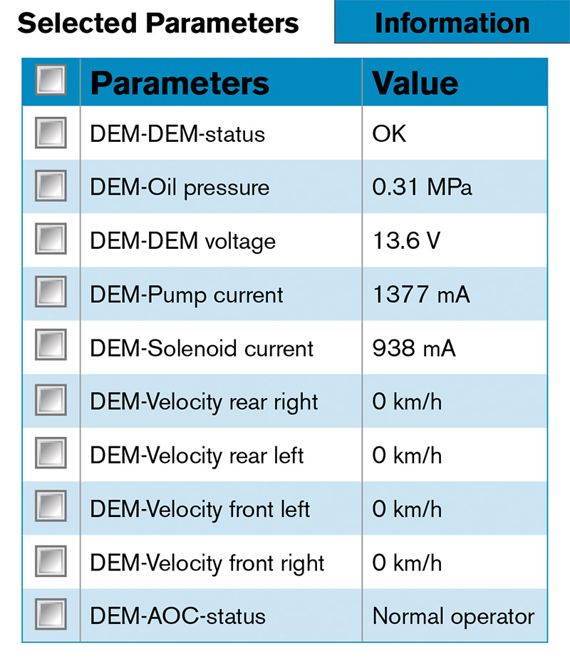
The following test can be performed using VIDA/Diagnostics/Vehicle Communications to indicate if a malfunction with the Temperature/Pressure sensor function can be detected. To test the function, DTC information and freeze frames have to be saved before DTCs are erased and then the DTCs can be erased. If the DTCs are not erased, the AOC functionality will be limited.
Testing for pressure sensor function:
- Ignition in position II, engine not running. Read out pressure to confirm function. Correct pressure 0.00 +/- 0.08 MPa (0.00 +/- 11.60 psi).
- Engine idling. Check that the AOC oil pump is running. Read out pressure info to confirm function. Correct pressure 0.38 +/- 0.08 MPa (55.11 +/- 11.60 psi)
Testing for temperature sensor function:
Ignition in position II. Read out temperature information. Normal value is ambient temperature when the vehicle is cold and 20 – 50 degrees C (36 – 90 degrees F) more than ambient temperature when the vehicle is driven.
If the Temperature/Pressure sensor indicates a malfunction when checked as described above, replace the sensor according to the Removal, Replacement, and Installation procedure in VIDA, erase DTCs, re-check the pressure & temperature using VIDA/Diagnostics/Vehicle Communications, and then test drive the vehicle.
There are two different Temperature/Pressure sensors available; an 80 bar sensor and a 40 bar sensor. The color of the sensor cannot be trusted to distinguish between the two sensors. As a guideline, chassis numbers that are found in VIDA parts catalog (once updated) can be used to distinguish between the two sensors as long as the AOC or DEM has never been replaced previously in the vehicle.
If a 40 bar AOC or DEM has been replaced, the vehicle now has an 80 bar sensor. If it has been replaced, the diagnostic hardware (HW) part number (P/N) must be read off in VIDA/Diagnostics/Network to distinguish between the two sensors.
If a 40 bar sensor is installed where it should be an 80 bar sensor, the sensor will indicate too high of a pressure. If an 80 bar sensor is installed where it should be a 40 bar sensor, the sensor will indicate too low of a pressure. To be absolutely sure that the correct pressure sensor is installed in the vehicle, use VIDA to read off the HW P/N.
If the vehicle is set up for an 80 bar sensor P/N 30759668, one of the following DEM HW P/Ns should be read out: 30759701, 30785483, 30759682, 30783198, 30735844, or 30783018.
If none of the above DEM HW P/Ns show up, the vehicle is set up for a 40 bar sensor P/N 30651694.
Care should be taken when removing the connectors from the DEM. Very little force is required to separate the connectors from the DEM without breaking the connector. When releasing the connector, press down on the connector, towards the DEM, to relieve pressure on the connector tab. Insert a small flat-blade screwdriver under the connector tab and gently rotate the screwdriver until the tab is unlocked. Then, gently push up on the connector.
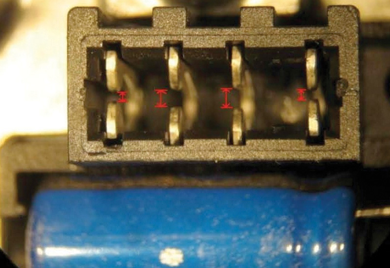
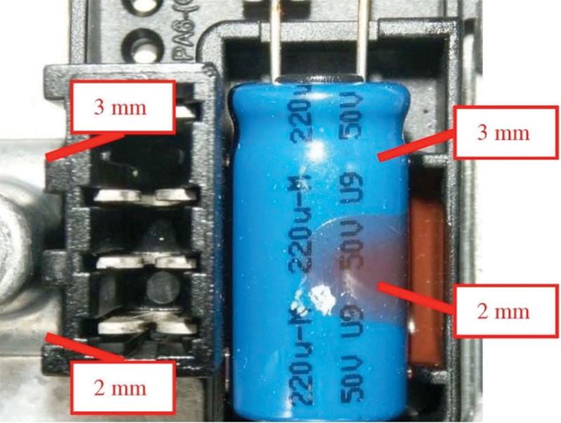
It is important to note the orientation of the Temperature/Pressure sensor in the DEM upon replacement. It is possible to forcefully install the sensor into the DEM in the incorrect orientation. Incorrectly installing the sensor will inhibit AWD function and can damage the DEM. See the photo (previous page) of the approximate dimensions of the connector and the female terminals in the DEM.
See the photo of a sample DEM that had an incorrectly installed Temperature/Pressure sensor. The center two female terminals are now spread apart due to the incorrect installation and the sensor will not make constant electrical contact with the DEM.
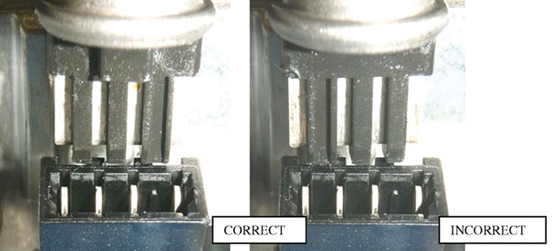
The photos below show the correct and incorrect orientation of the Temperature/Pressure sensor in the DEM connector.
The fault tracing and parts catalog information in VIDA are currently being updated to include this information.
Replacing the oil filter for the clutch (AOC)
Note! As the illustrations in this service information are used for different model years and/or models, some variation may occur. However, the essential information is always correct.
Removal
Caution! The oil filter must be replaced every four years. In the Service Schedule this corresponds to a normal mileage of 50K miles. However it is the period of 4 years that is the key factor, not the mileage.
Removing the oil filter
Note! Thoroughly clean around the oil pump before beginning removal.
- Position a container underneath the Active on Demand Coupling.
- Remove the two screws from the cover for the oil filter.
- Remove the loose o-ring furthest into the filter seat.
Installation
Installing the oil filter
- Clean the filter area thoroughly. There must not be any lint from any paper or cloths.
- Position a new o-ring furthest in the seat for the filter.
- Install the new o-rings on the cover. Lubricate the o-rings with a little Active on Demand Coupling oil, P/N 116 1641 (1 liter packs).
- Install the filter and the cover. Tighten to 5.5 N-m.
- Now fill the AOC through the fill plug hole until the fluid runs out, replace fill plug test drive to operating temp and then re-check fluid level and top off if needed.


0 Comments