
Electronic thermostats, multiple coolant circuits, and efficient flushing/filling.
History
Cooling systems in the modern automobile by and large still accomplish the original objective that they were designed to do: cool the engine and maintain it at an optimum temperature. Early systems were only concerned with the former. The internal combustion engine generates enough heat, so much so that if left unchecked it would melt the metal components and seize the engine in a short period of running time.
There have been basically 2 types of cooling systems in the automotive world – air cooled and liquid cooled. Air cooled systems have had a place in much of automotive history with the most iconic examples being the original Volkswagen Beetle, the Porsche 911 and the Chevrolet Corvair.
Automotive air-cooled engines are actually cooled by both air and oil. Basic cooling is provided by generous fins on the cylinders and cylinder heads which expose as much surface area as possible to the cooling air forced across them by an engine-driven fan. Located in the airstream often is some sort of heat exchanger to control the temperature of the engine. Control of the oil temperature was usually done with a type of oil thermostat that would control the flow of oil through a cooler.
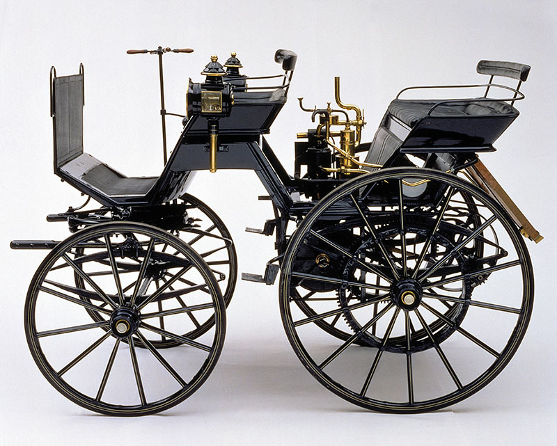
The earliest prototypes from Mercedes-Benz were developed by pioneering Germans Gottlieb Daimler, Wilhelm Maybach and Karl Benz. Herr Benz originally concentrated on two-stroke industrial engines, while Daimler worked alongside Nikolaus Otto at the Deutz firm that manufactured his engines.
Water has a higher heat capacity than air, and can thus move more heat, more quickly, away from the engine; however it involves more complicated and technically advanced engineering to get it flowing through the engine and regulated properly. Other than some early prototypes, Mercedes-Benz has stuck with the water cooled model for its production models.
Thermostats
As mentioned above, a way to regulate the temperature both to aid in warm up of the engine and control the combustion temperature was with the introduction of the coolant thermostat. The first thermostats used a sealed capsule of an organic liquid with a boiling point just below the desired opening temperature. These capsules were made in the form of a cylindrical bellows. As the liquid inside the capsule boiled, the bellows expanded, opening a sheet brass plug valve within the thermostat. As these thermostats could fail in service, they were designed for easy replacement during servicing, usually by being mounted under the water outlet fitting at the top of the cylinder block. Conveniently this was also the hottest accessible part of the cooling circuit, giving a fast response when warming up.
Today’s thermostats are usually located within a metal or plastic housing where the upper radiator hose connects to the engine. Most of today’s thermostats utilize the “reverse poppet” design, which opens against the flow of the coolant. These thermostats have a wax filled copper housing or cup that pushes the thermostat open against spring pressure. The wax thermostatic element was invented in 1935 by Sergius Vernet. As the engine’s coolant warms up, the increase in heat causes the wax to melt and expand. The wax pushes against a piston inside a rubber boot. This forces the piston outward to open the thermostat. Within 3 or 4 degrees F of the thermostat’s rated temperature, usually marked on the thermostat, the thermostat begins to unseat so coolant can start to circulate through the engine and radiator. It continues to open until engine cooling requirements are satisfied.
The combustion process in a passenger car engine runs optimally at an operating temperature of approximately 230°F. However, in older engines the engine temperature was kept below this ideal temperature level to prevent component damage from the high pressures needed to maintain this temperature without the coolant boiling away.
Conventional thermostats start to open at an engine temperature of approximately 110°F. It is fully open about 15-20 degrees above its rated temperature. If the temperature of the circulating coolant begins to drop, the wax element contracts, allowing spring tension to close the thermostat, thus decreasing coolant flow through the radiator and regulating coolant temperature.
Better control
Today’s engine thermostats play a greater role in increasing engine combustion efficiency and reducing emissions. Supplementing the mechanical function of the wax element, electrically-assisted thermostats incorporate an electric heater. This heater is controlled by the vehicle’s engine control unit (ECU), which receives information on the speed and load conditions of the engine. This data allows for precise control of the engine temperature, increasing combustion efficiency while reducing emissions, particularly during warm-up.
The controlling “map” or data set, stored in the ECU, is calculated by the engineers based on theoretical calculations and real-world measurements. Maintaining the engine at the optimal temperature under all conditions is the goal, and the electrically-assisted thermostat allows for this precise temperature control.
Electrically-assisted thermostats are fairly trouble-free, but external factors such as the use of low-grade coolant and failure to regularly service the cooling system can lead to material failure. Other failures may include mechanical sticking, as with a conventional thermostat, or failure of the heating element. The latter will set a diagnostic trouble code, aiding in the diagnosis of any faults. Generally the workshop manual will give a resistance value that can be checked with an ohmmeter.
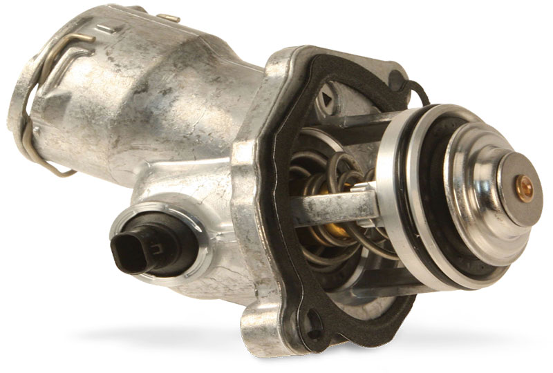
Replacement
Having determined a fault in the thermostat, replacement of the electrically-assisted thermostat is no different in terms of nuts and bolts than with a conventional one. Following the proper procedure is a standard guideline for this operation. Of course, paramount is using a genuine Mercedes-Benz part, unarguably the perfect match of fit and performance for the application.
Mentioned in the above paragraphs, these thermostats work in conjunction with a mapping component within the ECU. Aftermarket parts can trip you up and cost you time and expense you’ll regret in the long run.
Here is a rundown of the replacement procedure from the workshop manual for a 204 model; other models will be similar.
- Drain coolant at radiator.
- Remove left engine intake air duct and front engine cover.
- Remove upper coolant hose from coolant thermostat housing. Note: Be sure to replace the O-ring upon installation.
- Remove the poly-V belt and guide pulley to allow access to the thermostat bolts.
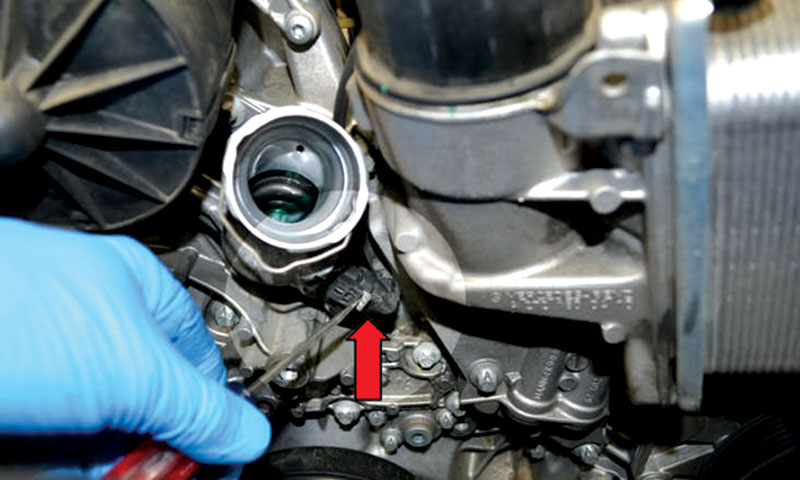
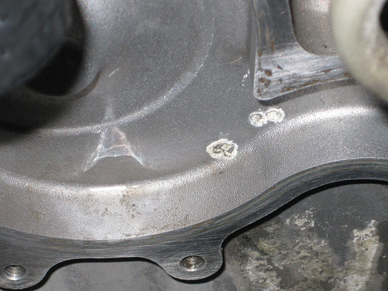
- Release and disconnect the electrical connector on coolant thermostat (see photo).
- Remove 2 bolts and pull coolant thermostat housing with coolant thermostat out of timing case cover.
- As usual, installation is the reverse order. Be sure the gasket surface is clean when installing the new gasket.
- Perform a function test on the coolant thermostat and check the system for leaks.
Draining, filling, and flushing
The maintenance interval for changing the antifreeze/coolant will vary depending upon the model year you are working on, but in newer Mercedes-Benz models it is 15 years for the first change, then every 2 years after that. To be sure, consult the maintenance book for the specific vehicle you are working on.
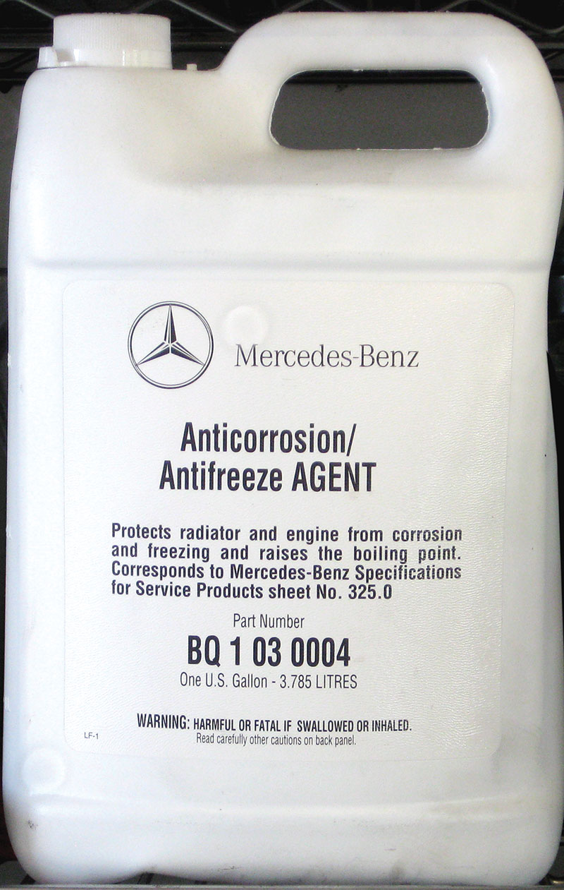
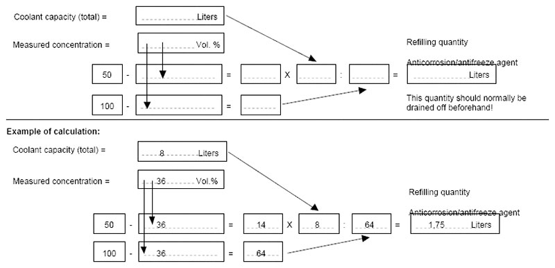
Whenever you are replacing a cooling system component, best practice is to renew the coolant at that time to avoid any contamination. The characteristics of the coolant should be checked at every service and during routine inspections. Mercedes-Benz recommends for passenger vehicles and some commercial applications a mixture of 50% by volume of water and antifreeze/anticorrosion agents, for protection down to temperatures of -37 F. Only use coolants that comply with specifications sheets 325.0, 325.2, or 325.3. Premixed coolant meeting specification sheet 326.0 can be used in engines produced up to April 2014. To find a list of approved coolants, visit the MB BeVo web site available from Daimler AG at bevo.mercedes-benz.com/beam.en.html, or search for “MB BeVo” in your favorite internet search engine, or download Daimler’s free “Specifications for Operating Fluids” app for iOS and Andriod.
A word about the water (see “Water Watch” StarTuned, December 2018): Clean water must always be used, and most drinking water will comply with the given specifications. Water that is too hard (has a high mineral content) is disadvantageous because of the possibility of scale or sludge deposits. Salt content, which is predominately chloride ions, will greatly promote corrosion. If you have no information available on the quality of the water in your tap, play it safe and use distilled or deionized water, or at least commercially-bottled water.
The aforementioned scale and sludge deposits typical when not following the specifications can result in overheating and deterioration of the cooling system. The radiator tubes will form scaly deposits which can block the flow of coolant. No amount of flushing will remove it once it’s there, the only remedy being to replace the radiator.
Corrosion of the metal components can wreak havoc as well and lead to serious and expensive repairs. Mercedes-Benz is the only passenger car/SUV manufacturer to build into the cooling system a slow-release protection device that on most late-model vehicles allows for a 15- year, 143,000 or 150,000 mile coolant replacement interval. The protection device – a packet of silica gel in the coolant reservoir – is designed to work with Mercedes-Benz specification coolants, and not others. Note that replacing the coolant reservoir gets you a new protection packet; otherwise, as mentioned previously, after 15 years the interval drops to 2 years.
I know fifteen years/150,000 miles seems like a long time. You might be thinking “That must be one of those new antifreeze products that fits all.” Well, despite anything you read about “compatibility,” most of those new antifreezes are not approved for use in Mercedes-Benz vehicles, for specific technical reasons. Stick with what’s best, or be prepared for the consequences.
If you’ve been in this business a while, you remember the traditional yellow Mercedes-Benz coolant. That changed to a blue coolant just after the turn of the 21st century, and modern models come with a pink coolant. With this variety of coolant types, Mercedes-Benz cautions the workshops to avoid mixing in coolants of a different specification sheet (color) in volumes greater than needed for topping off, or about 10% maximum. More than that, replace the coolant with all the same product.
Draining and filling is a fairly straight forward process. Here are the steps for the M271, M272, OM642, OM646, and OM651 engines:
- Slowly unscrew cap on coolant expansion reservoir, be careful of residual pressure.
- Remove lower engine compartment panels along with soundproofing.
- Slide drain hose onto drain fitting at radiator and drain coolant into a suitable container.
- Tighten radiator drain plug and detach drain hose from fitting on radiator.
- Remove coolant hose on coolant inlet fitting for coolant pump. This step is to help air enter the system to help drain the crankcase. You may be able to skip this step if having the cap off the expansion tank is enough
- Push drain hose on crankcase drain screw and loosen screw. (Not all engines have this.)
- Detach hose and tighten drain screw.
- Reinstall coolant hose on coolant inlet fitting if removed.
- Fill and bleed system. Use a vacuum bleeder/filler to avoid air entrapment, and speed up the process as well.
- Replace any removed panels.
Mercedes-Benz offers a special tool for vacuum filling under part number W285 589 00 21 00, although there are many similar tools available on the market.
Vacuum Filling and Bleeding
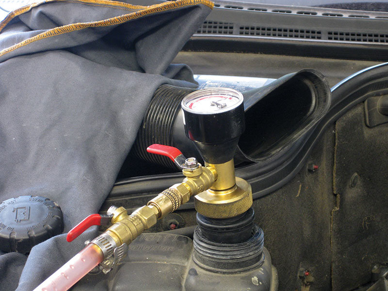
A vacuum filler is highly advantageous when filling a cooling system, as they pull the entire system down to a vacuum, and this vacuum will pull your coolant into the system, quicker than pouring it in and without adding unwanted air. While the system is at vacuum you can check the vacuum gauge to be sure there are no obvious leaks. Many a technician has started to fill a system, having left a hose off or a clamp undone, only to waste expensive coolant onto the ground.
One manufacturer claims to be the first and only tester developed specifically to run complete cooling system diagnostics with the engine running and at normal operating temperature and pressure. New patent-pending technology combines testing and monitoring of pressure, vacuum and temperature simultaneously, to provide real-time data far beyond the capabilities of a simple pressure tester. This combination of features ensures the most extensive, accurate cooling system diagnosis possible. The vacuum filling operation is fairly simple, most devices have similar steps:
- Attach the system valve and adapter to the expansion tank or radiator.
- Connect a shop air hose to the valve – make sure the valve is in the off position for this step. The valve uses a venturi to get vacuum from compressed air.
- Insert the suction hose into a premixed coolant container – have plenty of coolant ready to fill the system. The Mercedes-Benz tool has a large reservoir, big enough to accommodate most any cooling system without having to pause while swapping containers.
- Open the valve and pull a vacuum on the system. Observing the gauge, bring the vacuum down to about 25 inches. Most gages will have a marking to indicate the recommended vacuum level for testing and filling.
- Allow the system to rest, with the vacuum valve off, for 5 minutes while observing the gauge; this step will tell you if the system is tight. If not, disconnect and recheck your work.
- After vacuum has held for the proper time, open the valve on the suction hose and pull in the coolant mixture. Filling will stop when the system is full.
- Now either disconnect and check your system, or continue to use the tool to pressure and temperature test your work.
- Connect a suitable scan tool after you’ve filled the system and check for codes and proper temperatures during warmup. You may need to top off the system with a little coolant after your test drive.
Remember that several newer models have more than one cooling system. In addition to the conventional high-temperature cooling system, some models have one or more low-temperature cooling systems, for temperature control in systems not generating the kind of heat emitted by the engine. Vacuum bleeding ensures these systems fill properly, so don’t cut corners here.
Flushing Machines
The majority of flushing machines on the market today work under a similar principle, whether it is forward flushing or “back” flushing: a pump pushes the coolant mixture through the system until clean or full. The problem with most of these is they work on a principle of pushing the coolant against the thermostat spring to open it and then through the system. This principle works ok on conventional thermostats but is not practical on the newer electronically-assisted thermostats.
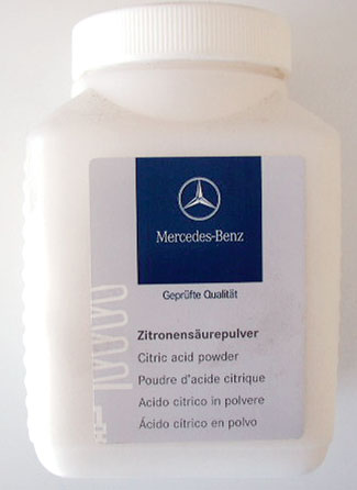
If you find yourself with a system that is contaminated and needs to be thoroughly flushed (as opposed to a drain and fill) then it is best to manually flush the individual components with a garden hose and clean water. You can drain the system in severe cases and add a descaler or flushing compound and then run the engine. To remove scale and sludge, or even engine oil in the case of a failed head gasket, use Mercedes-Benz cooling system cleaner A000 989 10 25 11, which is a citric acid-based product that is safe for all Mercedes-Benz vehicles.
After using the cooling system cleaner, you must completely drain all the cleaner and completely flush the system. Remove the upper and lower hoses from the radiator and run clean water through it, backwards and forwards, until the water runs clear. Do the same with the heater hoses.
The engine block will be more complicated because the thermostat will not allow you to push cool water through it. You will need to remove the thermostat and run clean water through the cylinder head and block until it runs clear.
Afterwards, completely drain the system and fill with the proper mix. A word on the heater core: this is an item that can get plugged due to lack of maintenance or incorrect antifreeze usage. Severe cases will require replacement, but the cooling system cleaner mentioned above, left in the system for a bit longer, and perhaps even repeating the treatment, is what Mercedes-Benz recommends. Flush thoroughly with clean water and hopefully you’ll have heater function again.
Proper maintenance, procedures and using the right products are the keys to successful cooling system service.
Download PDF


0 Comments