The Prius hybrid includes two separate cooling systems. Their roles are very different, as are servicing procedures.
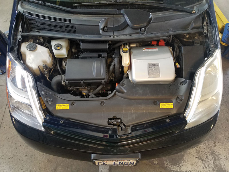
The second generation Prius (2004-2009) is equipped with several first-of-their-kind features. These features are designed to lower emissions and increase fuel economy. The most critical component affecting emissions and fuel consumption is the internal combustion engine, and its cooling system is optimized to these ends and includes several unique components.
This article covers aspects of the engine cooling system that are specific to the “Gen 2” in order to properly service and diagnose the vehicle. It concludes with a bleeding and diagnostic procedure to overcome the challenges that these special components present.
Two Separate Cooling Systems
The Gen 2 Prius has two distinct liquid cooling systems for the engine and inverter. It is critical to understand that they are separate before attempting any repairs.
Inverter Cooling System
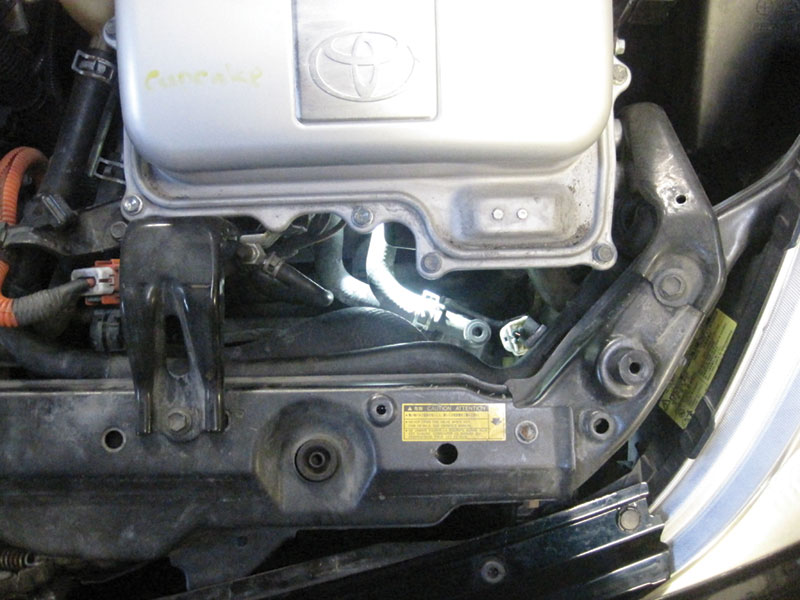
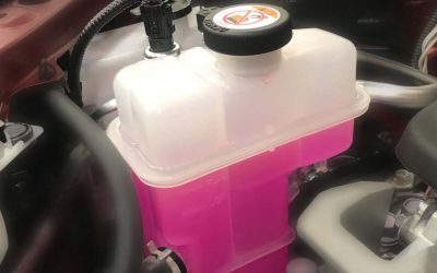
Locate the inverter cooling system beginning with the inverter coolant reservoir directly center in the engine compartment. The coolant specification is Toyota Super Long Life Antifreeze, pink in color.
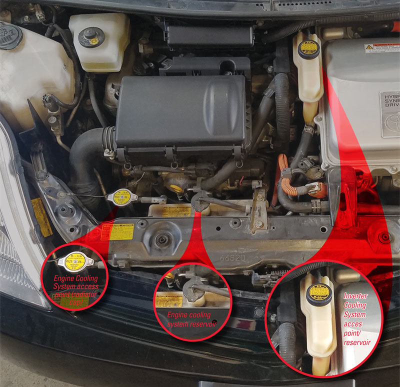
The reservoir is under a small amount of pressure and is integral to the coolant circuit. It bolts to the inverter assembly itself, the big silver box that reads “Hybrid Synergy Drive.” Coolant flows from the reservoir into the inverter, then out to an electric pump, through the transaxle, the radiator, and finally back to the reservoir.
The hoses that connect these components are the same size and share vicinity with the engine cooling system hoses, with the potential for misrouting, kinking, or cross-connection. Also note, while the inverter radiator is the same physical assembly as the engine radiator, the tanks/tubes are isolated and no liquid is shared.
Engine Cooling System
The engine cooling system occupies the majority of the radiator assembly, with access via a typical radiator cap on the top, passenger side. This is where to perform engine cooling system bleeding.
The cap and the overflow reservoir are mostly obscured by a plastic cover; the lazy observer sees only the inverter reservoir and assumes the systems are the same.
The radiator cools the engine like that in a conventional car, through two larger radiator hoses, a conventional thermostat, and mechanical water pump bolted to the engine. If that was all, bleeding the system would happen naturally.
HEAT = ENERGY
Things get interesting when we consider the hybrid scenario: an engine kept off as much as possible in order to conserve fuel. The Prius circulates coolant into the dash for cabin heating per usual. But it does so deliberately because heat created by the engine is not simply a waste product.
The engine may not be needed in various operating scenarios, but those scenarios have no relationship to when a passenger may demand heat. The engine therefore cycles independently of power demands in order to maintain coolant temperature as necessary. When the engine is off, the vehicle employs another electric water pump to circulate coolant through the heater core.
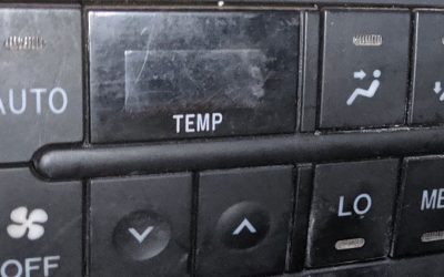
Fun fact: the Gen 2 Prius has extra “PTC” (Positive Temperature Coefficient) electric heaters built into the dash that kick in when the heater setting is on “high,” designed to assist in colder climates when the engine simply cannot produce enough heat.
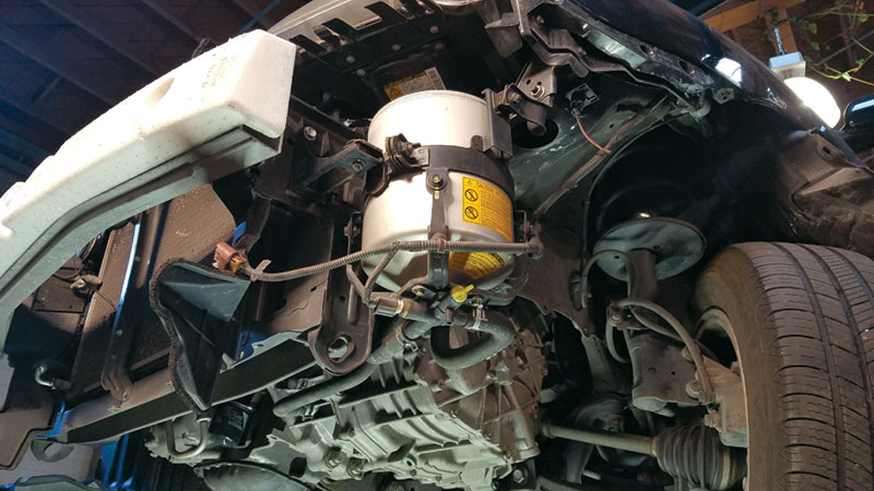
Keeping the cabin warm is not the only exceptional feature of a Prius. As part of its PZEV emissions rating, the system includes a thermos (called the “Coolant Heat Storage” or CHS tank) that can store coolant at 180 degrees F for up to 3 days.
When readied on, the driver may hear a faint whine while a third electric pump (at the thermos) runs for several seconds (prior to engine crank) to push hot coolant to the block, heating it to reduce fuel condensation, therefore lowering hydrocarbon emissions during startup.
Likewise the whine may be noticed when the car is turned off, pumping hot coolant from the engine into the thermos for storage.
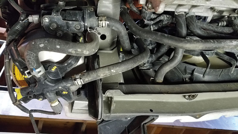
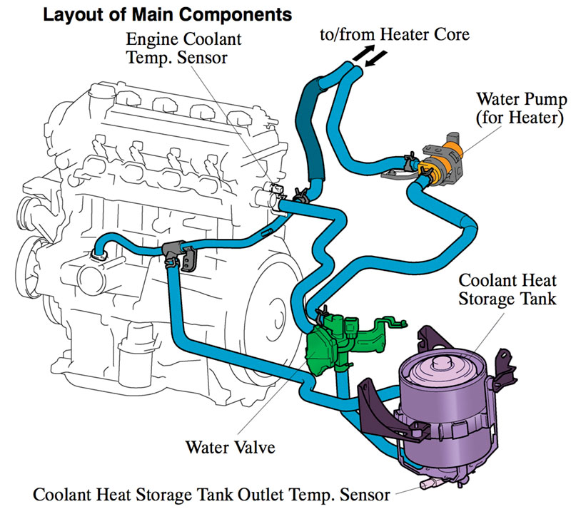
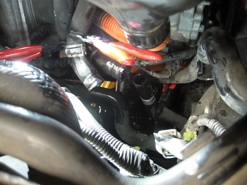
To manage both exceptional cases — cabin heating and engine warm up — the Gen 2 has yet another exceptional component: the so-called “water valve” (a.k.a. “three way valve”). This valve determines when hot coolant is circulated to the heater core, the thermos, or both. The three way valve is the gatekeeper to make sure heat isn’t wasted, but its existence in the system adds yet another layer of complexity regarding diagnosis and bleeding.
Three Way Valve
Coolant flows between the radiator and engine depending on a conventional thermostat only. For all other circulation, the three way valve determines the pathway:
[/fusion_text][fusion_table]
| Circulation Loop | PID Value | Active Test |
|---|---|---|
| Engine ~ Thermos | 2.5 V | Water Flow Valve 3 |
| Engine ~ Thermos + Heater Core | 3.5 V | Water Flow Valve 4 |
| Engine ~ Heater Core | 4.5 V | Water Flow Valve 5 |
The sole purpose of the thermos is to heat the engine before startup. When the car is shut off or turned on, therefore, the three way valve is in the first position in the list above. This is the state that corresponds with audible whining of an electric pump at the beginning or end of a trip.
The engine ECU commands the second position to test the function of the valve itself (more on this later) and to store hot coolant in the thermos during driving, once the engine is at operating temperature.
In all other conditions, to get the engine to operating temperature or once hot coolant is already stored, the valve is in the third position, to bypass the thermos and limit circulation to the heater core only.
Understanding these positions allows you to observe the data stream, confirm whether the system is operating properly and, more specifically, whether any air may still be trapped in the system.
DTC P1121 – A Common Problem
The three way valve is prone to sticking, setting DTC P1121. Sometimes the valve will stick in such a way that heat no longer circulates in the dash, but typically the only symptom is an illuminated MIL.
An active test allows you to command the valve in each position. However the test is only allowed key on (so you can’t control coolant flow at the same time), and on 2004-2005 model years, you only have a command PID (“Water Valve”), not a reported position.
On 2006-2009 model years you have two PIDs in the data stream: one for command (“Water Valve”) and one for actual position (“Direction Value 1”), to tell if the valve is doing what it’s told. On later models, therefore, you can command the valve to change in an active test (key on) and confirm whether the reported position corresponds.
On earlier models you can only confirm a sticky valve based on coolant temperature changes (or a lack thereof), as observed in data stream, when coolant flow is expected to change.
Often the three way valve will stick intermittently: the MIL will illuminate and then turn back off a few trips later. Don’t be surprised if the car arrives at the shop with the P1121 DTC in memory but the valve works fine. This is your opportunity to make sure there is no air in the system. If the system is full and circulation is normal, you can be confident that the problem is simply intermittent and sell a replacement part.
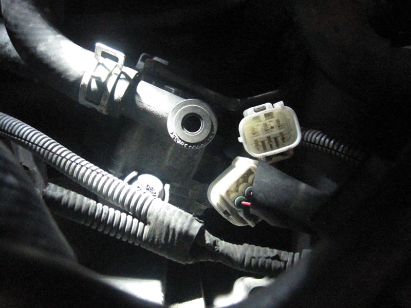
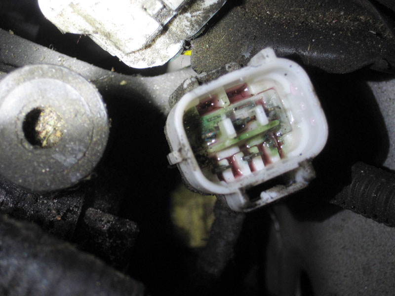
Left alone a faulty three way valve may develop an internal leak. Best case you will find evidence of coolant inside the connector (at the part itself) but the circuits through the connector are still functional. Worse is when the connector floods and shorts the reference voltage signal VC, shutting down the car and setting various DTCs for the myriad components that share the VC circuit. (Got a weird one on your hands? Check here!)
Some problems get so serious that pressurized coolant in the connector pushes into the wiring harness, corroding pins at the engine ECU all the way inside the dash. In that case the fix is the valve, the engine wiring harness, and a replacement ECU.
Upshot: even if the only apparent symptom is an intermittent MIL, it’s worthwhile to replace the three way valve right away.
Other Noteworthy Items
The Gen 2 mechanical water pump, at the front of the engine, is also prone to leaks; upon removal the engine will lose enough coolant to warrant a proper refill and bleeding procedure (described below).
Frankly, any time the engine cooling system is drained (collision work or whatever) it will likewise necessitate proper bleeding.
Older Gen 2s (especially those used as taxis) have a propensity to leak coolant through the head gasket and out the tailpipe. The result is an engine losing coolant (and accumulating air) ever so slowly, until it finally overheats. However no leaks are apparent upon inspection.
FYI, because the Prius cycles the engine frequently and depending on operating conditions, overheating conditions are typically limited to extended time at highway speeds. When it does overheat, the red triangle will illuminate on the dash and an overheating symbol will show up on the Multifunction Display, in the upper left hand corner. The car does not have a conventional dashboard indicator or gauge for coolant temp. Thus overheating can occur mysteriously to the driver.
DTC P1151 – Air in the system?
Air pockets will affect circulation through all loops. However the engine ECU will detect a lack of circulation specifically via the thermos, comparing the temperature values between the standard Engine Coolant Temp (ECT) sensor and the Tank Outlet Temp sensor mounted at the bottom of the thermos (CHS tank). If temperatures don’t correspond when expected, code P1151 will set.
The fact that air manifests in a thermos-related code highlights the sensitivity of that circuit to flow interruption. The thermos must be completely bled in order to circulate coolant reliably.
Note that this code will also set if the car is not properly bled after service, once the car is back on the road. It can also set when the electric pump that pushes coolant from the thermos into the block is inoperative. While it’s possible for the pump itself to go bad, this is usually caused by damaged wiring that runs down to the pump (behind the front bumper) after a front collision.
You can command the pump in another active test (“Water Pump”), listen for the whine, and follow up with circuit testing to isolate the cause. If the pump runs normally, also keep a look out for kinked or misrouted hoses.
Filling Procedure
Technicians were faced with byzantine cooling systems well before the 2004 model year. Hence the introduction of vacuum filling tools, which are extremely useful (if not essential) in the case of the Gen 2 Prius. If you replace the coolant during routine engine service (100K service, etc.), replace the mechanical water pump, or if you drain the cooling system for any other reason, then use a vacuum fill tool to refill the system for best results.
Once the system is filled, proceed to the bleeding procedure outlined below. Between the thermos, the three way valve, and the extra electric pumps and hoses, the chances you will not have air in the system (even after a vacuum fill) are extremely low. Always bleed.
Bleeding Procedure
Assuming the vehicle has a full or partially filled (air concern) engine cooling system, run the system through the following procedure:
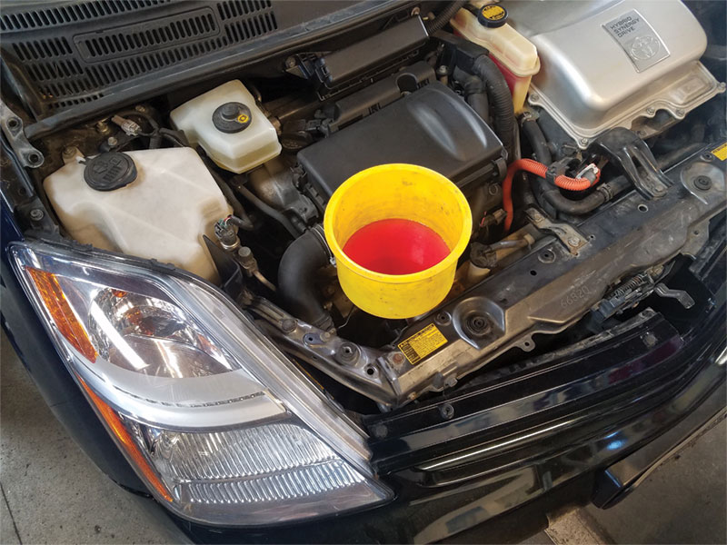
- Remove the radiator cap and attach a filling bucket. Add Toyota Super Long Life Antifreeze until there’s a resting fluid level in the container.
- Turn the vehicle key on (not ready on).
- Connect Techstream, select the Engine ECU, go to live data, and select the following PIDs:
- 2004-2005 Model Years:
- Coolant Temp
- Tank Outlet Water Temp
- Water Flow Valve
- 2006-2009 Model Years:
- Coolant Temp
- Tank Outlet Water Temp
- Water Flow Valve
- Direction Value 1(Water Flow/Direction Value = Three Way Valve)
- 2004-2005 Model Years:
- Narrow the PID list to the ones selected (long list to short list icon at bottom).
- Go to top menu bar and click Function —> Snapshot Configure.
- Set recording length to 60 minutes (or max); set trigger to “Begin.”
- Start the recording.
- Ready on and put a pedal depressor on the gas. (Without a pedal depressor the engine will turn itself off after a few minutes.) Set cabin temp to 80 degrees F and the blower motor on low.
- Initially the three way valve will be at 2.5 V. Once the engine starts the valve will move from 2.5 V to 4.5 V, allowing the engine to reach operating temperature.
- As the coolant temp approaches 180 degrees F the valve will move to 3.5 V and direct hot coolant to the thermos.
- Normally the valve will go from 4.5 V to 3.5 V three times to check the valve operation, then hold at 3.5 V to allow the thermos to sufficiently store hot coolant, and then finally return the valve to 4.5 V and allow the engine to continue warming up.
- At 190 degrees F the thermostat will open and hot coolant will circulate through the radiator, creating a slight dip in engine coolant temp.
- At 205 degrees F the radiator fans will cycle. If air flow through the radiator is proper, the engine temp will not exceed 205 degrees F.
NOTE: If the three way valve is stuck, if there is another obstruction, or if for any other reason air is trapped, the water in the bucket will rise and fall a great deal as the coolant temp changes (fans running, for example). Engine temp can also vacillate in data stream.
Assuming everything is hooked up and working correctly, leave the engine running and the bucket on the radiator. With the three way valve cycling, air will work its way out. Repeat warm up if necessary. - Once the radiator fans have cycled and the coolant level is stable in the bucket, the engine is bled.
- Stop the scan tool recording and save the file. Open the file and graph the recording with all PIDs overlapped. Set the temperature range for both the Coolant Temp and the Tank Outlet Temp to the same min and max (50 to 205 degrees F, for example).
When the system is working properly, the graph will capture all the relevant performance results of the engine cooling system:
- Three way valve covers all three positions.
- Coolant consistently circulates through the thermos, indicating air has been bled.
- Conventional thermostat opens at the proper temperature of 190 degrees F (evidenced by the slight dip in temp while the three way valve remains still).
- Cooling fans run.
- Radiator flow sufficiently removes heat in order for fans to cycle off.
Concluding Remarks
While Toyota’s design is robust in its effort to lower emissions, the Gen 2 Prius portends higher difficulty during service, for diagnosis as well as bleeding. Diagnosis is particularly dependent on bleeding procedure; without proper coolant flow it is impossible to validate other system functions.
The three way valve controls flow between components to make sure the vehicle doesn’t waste heat in places it’s not needed, given the operating conditions. That benefit is traded for another point of failure (the valve itself), to make service additionally complex.
These aspects remain special to the Gen 2 Prius; Toyota did not include them in Gens 3 and 4. Luckily there are plenty of Gen 2s out on the road and in need of service to make its mastery worthwhile.

0 Comments