
We take a close look at many of the most common electrical components we find in vehicles today and show how to test them to verify they really are faulty.
We’ve all had it happen: The Diagnostic Trouble Code (DTC) says it’s that part, the symptoms point to that part too, but after installing a brand new one…still the same problem. Ugh!
This article will take a close look at many of the most common electrical components we find in vehicles today and show how to test them to verify they really are faulty. We’ll also share some resources from Mercedes-Benz you can use to find test values for more complex parts like sensors. After all, we always want to find the “smoking gun” to be sure the car is really repaired.
A vehicle is assembled from many electrical and electronic parts, and different vehicle models use different parts. However, all electrical parts can be broken down into one or more sub-types, and each of these sub-types can be tested in generally the same way. In other words, there are only a few ways of checking components: Master these techniques and you can test almost any component there is.
Contacts
Whether part of a switch or a relay, electrical contacts all perform the function of closing or opening a circuit path. The characteristics of a contact that we can test are resistance, isolation and timing.
Contact Resistance: To measure contact resistance, we use either the ohmmeter (for relatively low-current contacts) to directly measure contact resistance, or the voltmeter (for higher-current contacts) to measure voltage drop under load. It is possible for a contact to show a low resistance under the light load presented by an ohmmeter, but have excessive voltage drop under load.
Contact Isolation: To measure contact isolation, we use an ohmmeter. It is possible to use a high-voltage insulation resistance tester (a so-called MegOhmmeter) but this would be unusual in typical automotive testing. An exception would be in certain high voltage systems such as found in hybrid vehicles and electric vehicles, where it is important to verify that the insulation resistance meets safety specifications.
Contact Timing: Contact timing can be checked by ear or sight, and for critical or precise tests an oscilloscope can be used. Generally, there should be no significant delay between mechanical contact actuation and contact electrical closure.
Connectors
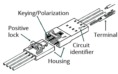
Connectors make it possible to disconnect electrical components from the wiring of a vehicle for maintenance or replacement, and allow for easier service by allowing one wiring harness to be separated from another. There are dozens of different connector types used by Mercedes-Benz, as you surely have learned.
As with switch or relay contacts, the important features of an electrical connector are contact resistance (through the connector) and isolation (between connector pins). We are less concerned with switching timing since connectors are not used for this kind of function, but intermittent contact can cause all sorts of strange symptoms.
In the case of a connector, we measure the contacts using the same methods as for switch contacts. In the case of high-current connections, a few tenths of an Ohm of resistance can be a problem, so ideally we measure the voltage drop across the connector while under load. In general, more than a few tenths of a volt drop is cause for closer inspection.
In addition, we must also look at the physical condition of the contacts: Are the contacts bent or malformed? Is there evidence of corrosion? Is the wire entering the contact properly crimped? Is there any physical damage to the connector housing or (if equipped) seal? Is the connector fully inserted and locked? Perform a careful inspection of the contacts, using a bright light and, if necessary, a magnifying glass. Often, connectors are buried in the car with difficult access, but it is important to get a good visual. We have resorted to using the shop’s borescope in some cases.
Fuses
Fuses protect electrical circuits from excessive current, and therefore from excessive heat build-up in wiring, connectors and other components.
Fuses are a subset of contacts. Although fuses are not designed to open and close repeatedly, they act like closed contacts when they are not “blown” or open-circuited. Fuses are tested either with an ohmmeter (to verify continuity) or by measuring voltage drop across the fuse, which should only be millivolts. If you measure volts, the fuse is faulty. With fuses, it is also important to check for the following:
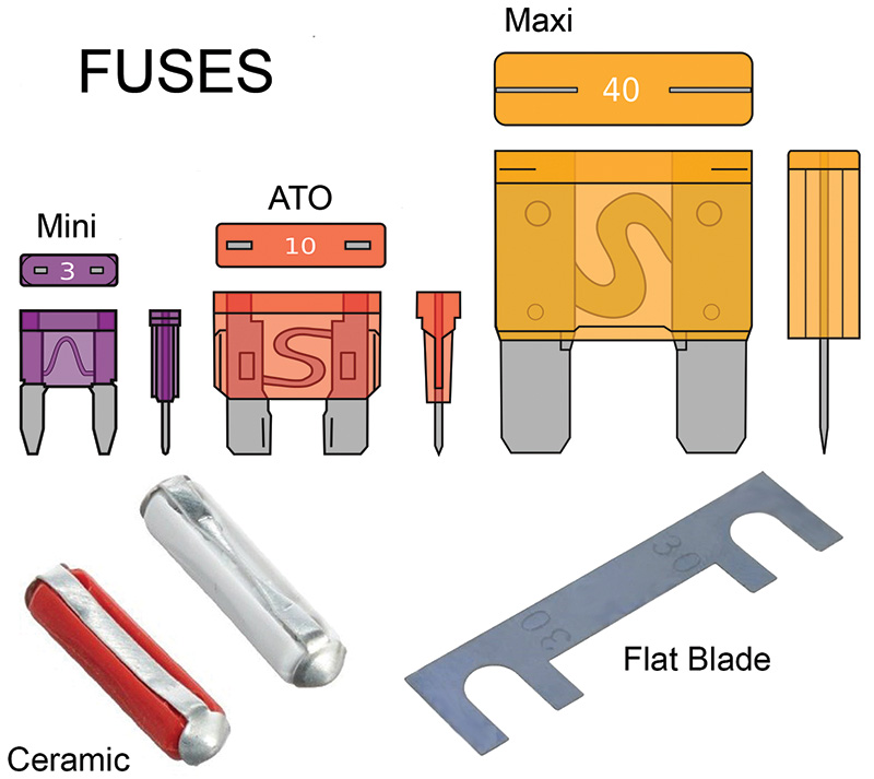
Fuse value: The fuse must have the specified value (in Amperes) to provide proper circuit protection. This is a safety item. Fuses are often color-coded as well as clearly marked with their rating. Always make sure the correct value fuse is being used, as verified on the wiring diagram or fuse card. Sometimes we have found the wrong value fuse installed.
Fuse type: The fuse must also be of the correct (physical) size and type, for example an ATO fuse with Nickel contacts or Silver contacts, designated with an N or S on the fuse. Types must be exactly as specified and not mixed since this can cause contact corrosion.
Contact corrosion: When the metal of the fuse contacts have deposits on them, it often causes high contact resistance. This can lead to fuse heating and low circuit voltage.
Proper insertion: If the fuse isn’t seated in its contacts well, it can cause high resistance.
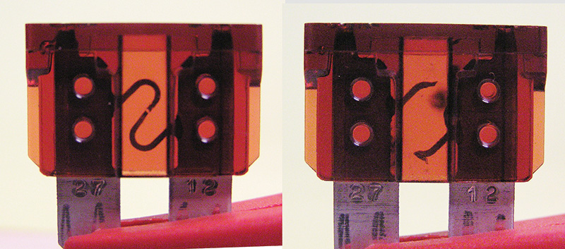
If a fuse has blown, as shown in the near-by photo, look at it. A longer-time, moderate overcurrent often creates a small, sometimes difficult-to-see break in the fuse material, as seen on the left. Compare that with a shorter-time, high overcurrent which ‘blows’ the fuse visibly, as seen on the right. Knowing what kind of overcurrent a circuit with an open fuse may have faced will help in determining how to correct the fault.
Wires
Hundreds or thousands of feet of wire are used in modern Mercedes-Benz models, however much less than the number of functions in the vehicle would require if there were no networks (such as CAN) used in the vehicle. When checking wires, be sure to consider these points:
Check for continuity end-to-end. Note that this usually includes a connector on each end, and perhaps one or more connectors in-between, so be mindful that these also need to be checked. Always use the correct adapter from the electrical connection kit.
Check the wire’s physical condition. You’re looking for damage to the insulation or a connector, excessive bending, and for network wiring the evenness of the ‘twists’ in the wire pair. Also check that the harness is not placed in a position where it can be damaged.
Verify the wire’s current-carrying capacity. Your ohmmeter may show continuity, but when carrying a few Amperes of current the resistance may be too high due to broken wire strands. As with connectors, check the voltage drop of the wire under load, it should be just a few tenths of a volt at most.
Although rare, remember the possibility of an improper wire repair or incorrect connector pin or socket placement. You never know who has been in there before you.
Lamps and Lighting
Incandescent light bulbs, invented in the early 19th century, are little more than a wire that glows white-hot, giving off light. Testing a light bulb is similar to testing a wire: If it has continuity it is essentially functional.
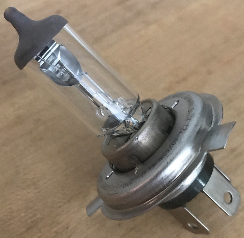
Some incandescent bulbs are filled with pressurized halogen, an inert gas. Halogen bulbs are different from regular incandescent bulbs in three important ways: First, they operate at a higher temperature, which improves efficiency but also increases the danger of being burned if you touch a hot light bulb. Second, they operate at a higher pressure, also for better efficiency. If the bulb breaks, the higher pressure may propel the bulb shards in a dangerous way.
The clear bulb is made of quartz (fused silica), which is tougher than regular glass but sensitive to any contamination (such as oil or grease from skin contact) that can allow localized heating and lead to shattering. For these reasons, halogen bulbs must be handled with greater care. Never touch a halogen bulb, always use a clean cloth or paper. If accidentally touched, wipe the bulb clean with isopropyl alcohol and clean cloth or paper.
A High-Intensity Gas Discharge (HID) Lamp, the so-called Xenon headlamps, do not contain a wire filament. Xenon lamps use the light from an electrical arc within a bulb filled with xenon gas. This type of bulb does not have a filament, and cannot be tested using continuity or any other means. The simplest option is to try a replacement lamp.
A high voltage is used to ignite the arc, which reduces (but is still dangerous) once the arc (which is a conductive plasma) is formed. Because xenon headlamps operate at high voltages, there is a risk of electrocution. Read and follow the safety information in WIS.
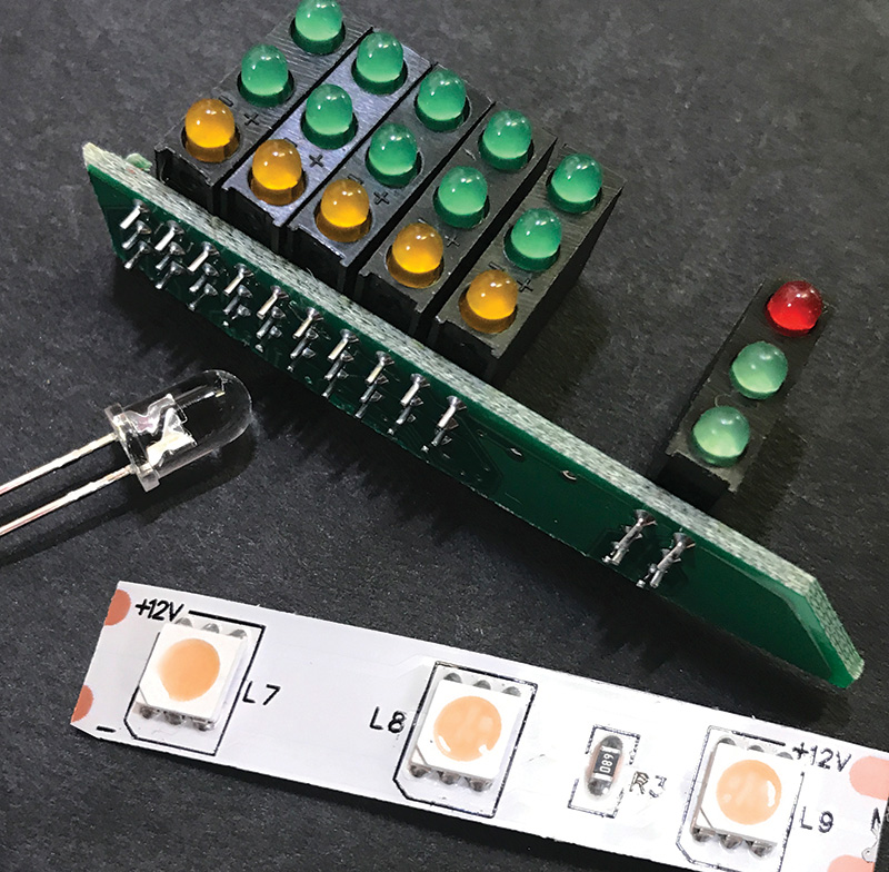
A Light-Emitting Diode (LED) is a semi-conductor diode that emits light. The electrons in the power source excite the atoms in the semiconductor to a point where they have excess energy. When that energy is released, it comes in the form of a photon, as light. Since an LED is a diode, it conducts electricity in only one direction. Unlike ‘regular’ diodes, the reverse voltage an LED can withstand is not very high, a few volts at most. To test an LED, apply the rated voltage (see below) of the correct polarity and see if it lights.
In automobiles, we do not see individual LEDs like those available at the electronics store (pictured on page 4), but instead complete assemblies set up for a 12 Volt power supply. For low-power LEDs, this can be as simple as a few LEDs and a voltage-dropping resistor. For high-power LEDs, such as those used in headlights, an electronic LED controller is used to ensure the LEDs receive very precise power.
The operating voltage of an LED is determined by its color: Red and orange LEDs operate at about 1.9 to
2.1 Volts, while white LEDs operate at around 3.5 Volts. Even a slight over-voltage – about double the operating voltage – will damage the LED.
The voltage-dropping resistor or electronic controller is essential for LED operation. Although 6 red LEDs in series will operate from 12 Volts, as the LEDs get warmer they will draw more current. This additional current increases the temperature further, and a cycle called “Thermal Runaway” begins, leading to LED failure. The resistor limits the voltage to each LED by dropping more voltage as the current increases (according to Ohm’s Law), stopping thermal runaway.
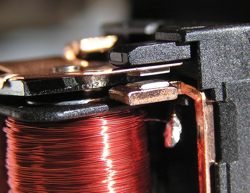
Coils
Coils of many different types are used in automobiles. Most of us are familiar with ignition coils, which are in fact transformers, used to generate the high voltages needed for spark plugs to operate. Relays, solenoid valves, solenoid actuators and motors all use coils as well, and all have similar tests.
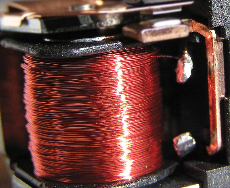
An electronic coil is simply a coil of wire, thus the name “coil.” And, like wires, they are fairly simple to test (at least at the technical diagnosis level) with an Ohmmeter. In some cases, other testing such as current consumption or voltage drop may be helpful.
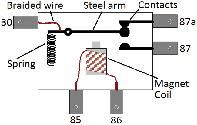
When an electrical current passes through a wire, it generates a magnetic field, just as a magnet passing a wire generates electrical current. If we make a coil of wire, the magnetic field is concentrated and can be used, for example, to move the magnetic ‘armature’ of a relay or solenoid valve. This allows us to use a relatively small current (through the relay’s coil) to switch a much larger current (through the relay’s contacts).
Although a modern ignition coil is indeed a coil of wire (two coils, actually, forming a transformer), because they contain electronics they cannot be tested except installed in the vehicle and by running the engine. Here, we use XENTRY Diagnostics and an engine scope to watch the secondary ignition pattern.
Sensors
Electronic systems in automobiles have a goal of making the vehicle better in some way: Better safety, better convenience, better efficiency, better comfort, and so on. In order to operate, systems often need to know the value of some physical quantity or another. For this we use Sensors.
Sensors can be used to measure most any physical quantity: Temperature, pressure, light, physical position, speed, and so on. While the specific theory of each sensor’s operation can be a topic for an entire book, from the technician’s point of view we are only concerned with one thing: Does the sensor accurately sense what it should?
This means we must know two things about the sensor to test it: What is it sensing, and How does it report its readings.
Most of the time, what the sensor is sensing is clear, but sometimes how it is sensing it is not as clear. Take a wheel speed sensor for example: It is supposedly sensing wheel speed, but what it is really sensing is ‘teeth’ passing the sensor. The difference is that looking at a moving wheel, you can see it has “speed” but you can’t see that the spaces between the teeth are filled with debris, resulting in a wrong speed value.
The point is, knowing exactly what a sensor is sensing (teeth) is important when deciding how to test it, while knowing what parameter it is sensing (wheel speed) is important when deciding which sensor to test. Once the sensor to be tested is identified, you need to determine how these readings are reported back to the control unit, so you can measure it and decide if the sensor is sensing and reporting what actually exists.
Temperature
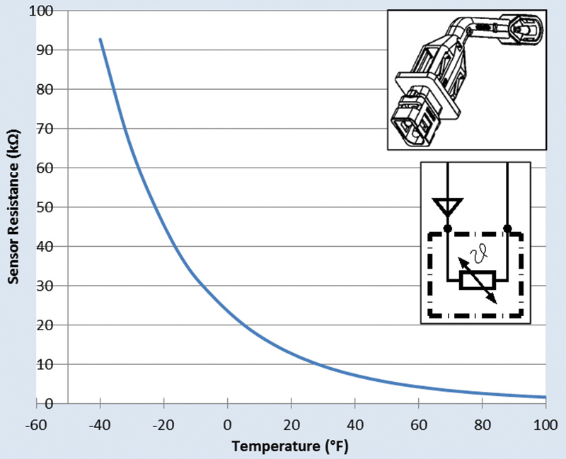
The graph shows the resistance of a particular sensor, according to the temperature it is sensing. It has a Negative Thermal Coefficient (NTC), meaning that resistance decreases as temperature increases.
To test it, disconnect it and use an ohmmeter to measure resistance, and compare it to the actual temperature at the sensor, ideally at a few different temperatures. Ice in water is about 32 F and hot water from the sink is often around 120 F.
Many sensors in newer vehicles are supplied with +5 Volts and return a signal that varies between around 0.5 to 4.5 volts. Note that some sensors have voltage outputs that are not referenced to ground but to +5 volt power. Measuring with your voltmeter with a ground reference will lead to major confusion, as the readings will be low and not make any sense. Always try using the +5 volt power supply as the reference to see if that makes a difference. Hall-effect sensors such as wheel speed sensors are one of the most common parts that use a +5 volt reference for the output signal.
Finding Test Values
When you need to know the test values for a sensor, use the following resources (listed in order of success):
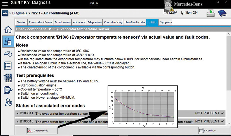
- XENTRY Diagnostics: Enter the control unit the sensor connects to and look for a guided test, which usually has the specific test values.
- WIS: Find the Function Description (document type GF) for the system, which may include information on the sensor. Although WIS very rarely contains test values – this is exclusive to XENTRY Diagnosis – the function description can help you better understand the role the sensor plays overall.
- Test a known good sensor, under conditions that are known (e.g., temperature, pressure, etc.) and compare readings.
Conclusion
So there you have it: Even though that fault code says that Component XYZ is faulty, that “ain’t necessarily so.” Take a few extra seconds to actually test the component, verify that it really is faulty and see what that can tell you about the reason for failure. Understanding the component’s function will definitely help you figure out how to test it, and with a few simple tests, virtually any electrical component can be verified good or bad, not only ensuring that the correct part is replaced, but saving you time and effort as well.


0 Comments