
Ground isolation is a concept that many technicians have a hard time with. We’re used to vehicles with 12V negative-ground electrical systems, and it’s hard to stop thinking in those terms. However, high voltage systems are never chassis grounded, and if a high voltage cable or component shorts to chassis ground, it’s a problem.
Why Aren’t High Voltage Systems Grounded?
High voltage systems in hybrid and electric vehicles are very safe. Ground isolation is one of the ways hybrid vehicles are made safer. There are plenty of places where a person can come in contact the body of the car. If the high voltage battery were chassis grounded, a person could be shocked if he were to touch a live wire and the body of the car at the same time. With no chassis ground, a person must touch two sources of high voltage, a positive and a negative, which is less likely.
This means that two cables must be run from the battery to the inverter, and that the motor/generators aren’t center tapped and aren’t connected to ground.
What Happens When There’s an Isolation Fault?
All Toyota hybrid vehicles 2004 and newer will prohibit restarting the vehicle if the HV ECU detects an isolation fault. If an isolation fault occurs, the driver will be alerted with a malfunction indicator, but he will be able to continue driving to his destination. Unlike a 12V short to ground, there’s no danger of fire or blowing a fuse with a high voltage short to ground.
When an isolation fault is detected, the trouble code P0AA6 (Hybrid Battery Voltage System Isolation Fault) will be stored. Also, an information code 526 will also set at the same time. Once the driver tries to restart the car, the HV ECU will perform testing to find out which section of the high voltage system is shorted to ground. This results in a second location-specific information code. This code will save hours of diagnostic time and it should be your goal to find this second information code.
Diagnosing Isolation Faults
The first step is to find the second location-specific information code. Sometimes, a car will only have the first information code, 526. This can happen because isolation faults can be intermittent, and the fault may not be occurring when the driver attempts to restart the car. For instance, if a fault occurs while driving and then the car is parked overnight, the fault may not still be present when the driver attempts to restart the car, and the second INF code may not set.
If this happens, run a Health Check and click the “save all information” box, then clear codes and drive the car. Hopefully the fault will occur during your test drive. Be sure to have the air conditioning on during your drive because an electric air conditioning compressor may be the source of the fault. Also, try to get the HV battery state of charge high (60% or over). Isolation faults are more likely to occur when the SOC% is high.
Once the warning lights come on, pull over immediately and then turn the car off and then start it again. It won’t Ready, but it will run the self-test. Sit patiently for a few minutes and give the test time to complete, then run another Health Check. If you get your second INF code, great.
Save your data (once again, make sure the “save all data” box was checked when you ran the Health Check). Don’t worry, you’re not stranded. With your data saved, you can safely clear codes and then you’ll be able to drive back to the shop.
Location, Location, Location
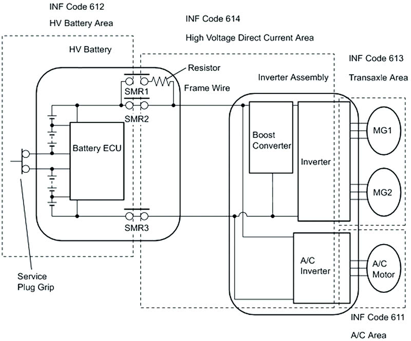
The first generation of the Prius didn’t give you a fault location. The only way to determine the location (short of manually testing everything) was to energize sections of the high voltage system one at a time. Only the battery has power with the key on and engine off. While Ready in neutral, only the battery, DC cables, and inverter have power. Ready in reverse adds in the two MGs. This is a little similar to what the later hybrids do automatically with their self-diagnostic routine.
Most Toyota hybrids have four or five P0AA6 information sub-codes. Each one points to a different section of the high voltage system and provides you with a good place to begin manual testing.
| INF code | Description |
|---|---|
| P0AA6 – 526 | You can safely ignore this INF code. It sets any time the P0AA6 sets and provides no additional information. |
| P0AA6 -611 | This INF code indicates a short to ground in the electric air conditioning compressor, cables, or connector. It’s very important to run the A/C during your test drive, otherwise this code won’t set, and you could drive forever and never duplicate the fault. |
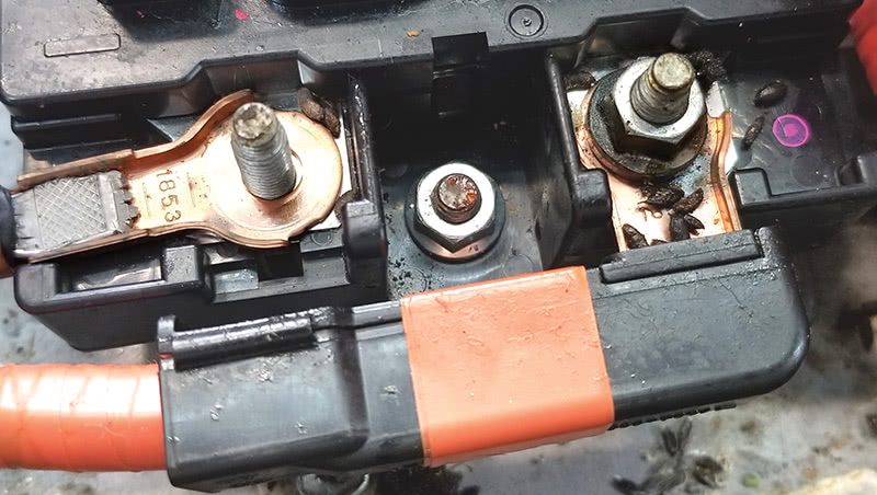
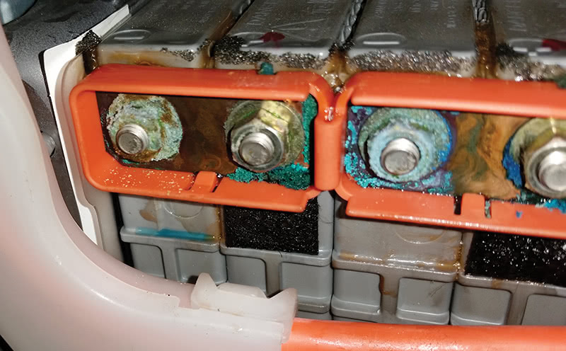
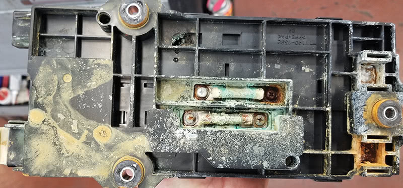
| P0AA6 – 612 | If the fault is on the battery side of the system main relays, an INF code 612 sets. Look for electrolyte leaking from the battery terminals, mouse urine (it’s pretty conductive), or tools left in the case from a prior sloppy repair. |
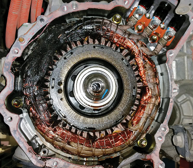
| P0AA6 – 613 | INF code 613 indicates a fault with the motor windings, motor cables, or output side of the IPUs. This will typically be caused by a motor/generator winding grounding to the stator back-iron. |
| P0AA6-614 | If there’s a fault with the DC cables going from the battery to the inverter, or the inverter itself, INF code 614 will set. DC cables can be damaged in collisions. Since they are shielded cables and the shielding mesh is grounded, damage to the insulation between the cable and shielding can cause an isolation fault, sometimes with no visible signs. Faults in the inverter are usually due to coolant or other foreign material in the inverter. |
| P0AA6-655 | 655 is only found on all wheel drive vehicles. Toyota uses an additional motor/generator to drive the rear wheels on many AWD models. |
Newer vehicles are using seven-digit trouble codes, and additional information that is included in the INF code is part of the seven-digit code.
- P0AA649 = P0AA6-526
- P1C7C49 = P0AA6-611
- P1C7D49 = P0AA6-612
- P1C7E49 = P0AA6-613
- P1C7F49 = P0AA6-614
The concept is the same, and the change in format doesn’t really matter. No matter how familiar you are with a system, always check the service information first. Things do change and it’s important not to make assumptions.
Manual Testing
Once you’ve gathered information with the Techstream, it’s time for manual testing. Isolation testing is performed with an insulation test meter, often called a megohmmeter or Megger. Since isolation faults are contact between an insulated high voltage component and chassis ground, the insulation test meter is always connected to the high voltage component under test and any metal part connected to ground.
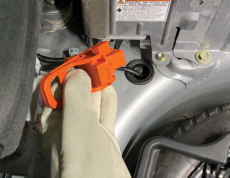
A megohmmeter is an ohmmeter, just like the ohmmeter on your multimeter, or the milliohm meter used for testing winding resistance. The difference is that it measures components with very high resistance, whereas a multimeter ohmmeter measures medium resistance, and a milliohm meter measures very low resistance. Like all ohmmeters, the megohmmeter is used with the component de-powered and disconnected. Therefore, you always start manual testing by removing the service plug.
An insulation test meter has a voltage range setting. It’s important to select the appropriate range, which is found in the P0AA6 diagnostic chart on TIS. Selecting too high a range can damage the inverter or AC compressor on some models. Selecting too low a range can make a bad component appear good. Most Toyota models are tested at 500V, but both battery and boosted voltages are higher on new models, so check the service information first.
Testing the HV Battery
There are two problems with testing the HV battery for leaks with an insulation test meter. First, the battery control unit usually needs to be disconnected during testing, so if it were the source of the short, there’s no way to test it. In the real world this doesn’t seem to be a problem though. The other issue is that the battery cover must be removed to perform testing, and often the source of the short is the foam air dam on the battery cover. You’ll need to rely heavily on visual inspection if you have a P0AA6-612
Testing the Motor/Generator Windings
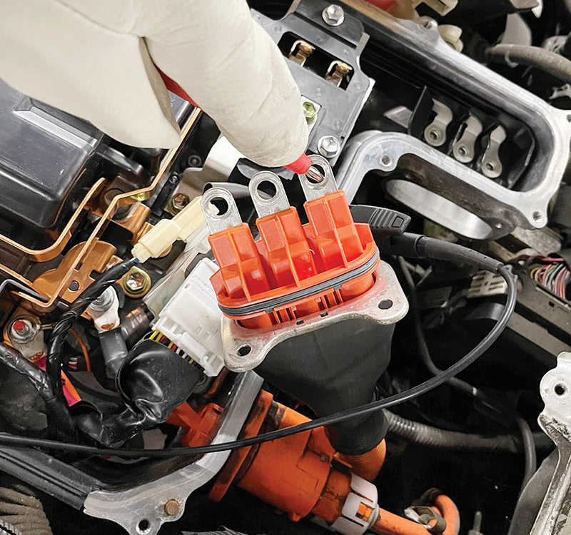
MG windings are tested from the 3-phase cables under the inverter cover. The cables must be removed from the inverter terminals for testing. The service manual says to connect the negative lead from the meter to the inverter case or other ground point, and the positive lead to each of the 3-phase cables one at a time. It’s not really necessary to check all of the cables since they are all electrically connected. If one has a short, they all will have shorts. If one tests good, they will all test good. That said, testing the other two only adds 10 seconds to the job, so why not.
Testing the Inverter and DC Cables
The diagnostic procedure for INF code 614 usually requires disconnecting the DC cables from the inverter and testing them with the insulation test meter. If OK, check the DC cable terminals on the inverter with the meter. The resistance of the inverter will be lower than any other component, but as long as it’s greater than what’s specified in the manual, it should be OK.
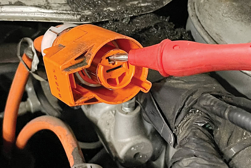
Testing the Air Conditioning Compressor
The AC compressor is tested the same way as the MG1 and MG2. Disconnect the 3-phase cable and check between the cables and ground.
A note on electric AC compressors and AC oil. Everyone should know that hybrids need ND-11 AC oil, and ND-8 shouldn’t be used. However, many people have “gotten away” with using the wrong oil, or not flushing the machine, and are now convinced ND-11 isn’t necessary. One day it will catch up with them.
Here’s why. When the AC compressor is new, and the winding insulation is in great shape, the wrong oil may not cause a short right away. However, as it ages and the insulation degrades, a loss of isolation may occur. Now, imagine a car comes into a shop and a tech put the wrong oil in, just like always, only this time, the winding insulation has worn away a bit more. The ND-8 now causes a short, and a P0AA6 sets, and the car can’t be driven anymore.
Short Wave Highest Val
Isolation faults can be intermittent. Sometimes the PID “Short Wave Highest Val” (SWHV) can help find intermittent faults. For a P0AA6 to set, a fault must be present for at least 60 – 90 seconds. If the problem comes and goes, you have difficulty getting codes to set. Monitoring the PID SWHV will show you when a fault occurs, even if it’s not happening long enough to set a code. However, it can be a little tricky, so read the next part carefully.
Short Wave Highest Val is a voltage between 0V and 4.98V. Normally it will be over 4V. When its value is 0V, there is a dead short between high voltage and chassis ground. However, it’s only valid when the boost converter isn’t operating.
To determine whether the boost converter is active, check the PIDs VL (voltage low) and VH (voltage high). VL is the voltage at the DC cables in the inverter. VH is the voltage on the boost converter output. If the voltages are roughly equal, the boost converter isn’t active, and you can use SWHV for diagnosis. On the other hand, if VH is higher then VL, ignore SWHV because it will look like there is a fault, even though there isn’t.
The easiest way to use SWHV is to graph SWHV, VL, and VH, that way you can easily analyze the data from a test drive.
0 Comments