
Understanding the fundamentals of electricity and electronics signal behavior can make or break your diagnosis. No matter how advanced we are in our knowledge in the ‘theory’ of things automotive.
Diagnosing and repairing Mercedes-Benz vehicles successfully in the modern era requires a well-rounded, focused technician, with a solid grasp of electronics control theory, mechanical prowess, as well as bit of chemistry and geometry too. Serious automotive technicians we train with today also have an insatiable thirst to learn, to keep up with the technological leaps that excellence and advancement in Mercedes-Benz engineering bring us. But no matter how hard a technician studies vehicle system theory, fuel controls, network communications, programming and all of the high-technology focus Mercedes-Benz vehicles require, from time to time we get that one car in our bay that challenges everything we know.
The diagnostic disconnect here for most really good technicians we work with is that underneath all of the signal processing theory, computing and software, there are real-life physical electrons running around, providing seamless electromechanical control of all vehicle systems… until those electrons go rogue. And most of us were never taught how to understand and quantify electrical behavior via measurement before we were jumped into some really high-tech stuff. Understanding the fundamentals of electricity and electronics signal behavior can make or break your diagnosis, no matter how advanced we are in our knowledge in the theory of things automotive.
Measurement and Signature Intelligence (MASINT)
Signature refers to the electrical characteristics that make up a signal. These signals are measured (the Measurement part of MASINT) with oscilloscopes, meters, specialty RF detection equipment and other signal processing systems. We analyze the signature of these signals to gain information (intelligence) about the signals.
This is literally our world. We are Automotive MASINT Specialists. But many of us—even the most experienced amongst us, need to go back to first grade, metaphorically speaking, to learn how to calculate 1+1 before we try to master trigonometry.
Automotive technicians perform their MASINT work in the analog realm, but we are measuring and analyzing signals that dictate whether the digital realm functions or not; this is where even the most highly-trained, advanced automotive technicians should always stay focused on developing better MASINT skills because this is how diagnostics are done when all of the scan tool and programming magic fails to solve the fault.
Remembering The Basics
Most technicians have not been properly taught electrical and electronics fundamentals as they were “trained” into the high-tech automotive business. We’re talking the basics of electrical measurement, and the basics of electronic control mechanisms, and, more importantly, the electrical behavior and the resulting signatures they provide for the technician to truly identify the fault and get the vehicle repaired correctly the first time.
Just try to get any automotive tech to sign up for a class on basic electrical fundamentals and you’ll see a class with three people in it. Most of us believe we are far too advanced for a basic class, yet in the arena of hands-on diagnostics this is the type of training we all need most.
But because of this paradigm, a strange pattern started to emerge in our internal data: In the overwhelming number of support cases we solve that are what we call “Deep Study Cases,” it turned out to be a very basic fault, masked heavily by high technology. In our remote technician support realm we lean heavily on MASINT every day to get the answer on these cars.
When it comes to measuring circuits, in general terms, most technicians have figured out how to connect an oscilloscope and acquire the needed signals for most diagnostics—a camshaft and crankshaft sensor signal set, for example.

But what are these signals, what are they made up of… where did they come from, how were they physically (electrically) derived? This can be part of the disconnect in diagnostics that directly ties to why one gets “stuck” in any given diagnosis. Our recent tussle with a 2011 E350 with rogue electrons proved this to us in a big way.
Sometimes what would seem to be the simplest of diagnostic scenarios we could face turns out to be a huge challenge: the research, the disassembly for testing, the gnarly intermittents. Such was the case here, and that can be very difficult to track down. Often a technician will struggle to identify the fault because they either didn’t take the time to research, prepare and set themselves up for diagnostic success, or maybe test plan guidance was vague, circular, or confusing.
With the complex network and systems diagnostics in Mercedes-Benz vehicles (quite frankly no matter what the badge on the front of the vehicle), the time spent in research and preparation of your diagnostic approach is often more important than any time we spend physically testing the vehicle. But maybe we are dealing with rogue electrons here, and if that is the case, then rest assured, all bets are off for published diagnostic test plans anyway. I speak with authority and passion on this point because in most of our daily remote support calls, we get to deal with the rogue electron cars.
This E350 was exhibiting a very strange problem, which was presenting as a condition where a whole string of multiple 5-volt-reference sensors were setting circuit high limit and signal plausibility DTCs. Too many to list here, and for the purpose of this discussion, there is no reason to waste space listing the DTCs and diagnostic test plans. Several different service facilities had looked at this car and had not yet been able to identify the source of the fault but had recommended component replacements as a means to solve the issue. (We lovingly call this “The Parts Cannon.”) The customer got concerned at this ‘diagnostic’ approach suggested by at least two locations, then landed at our client’s shop for a third opinion.
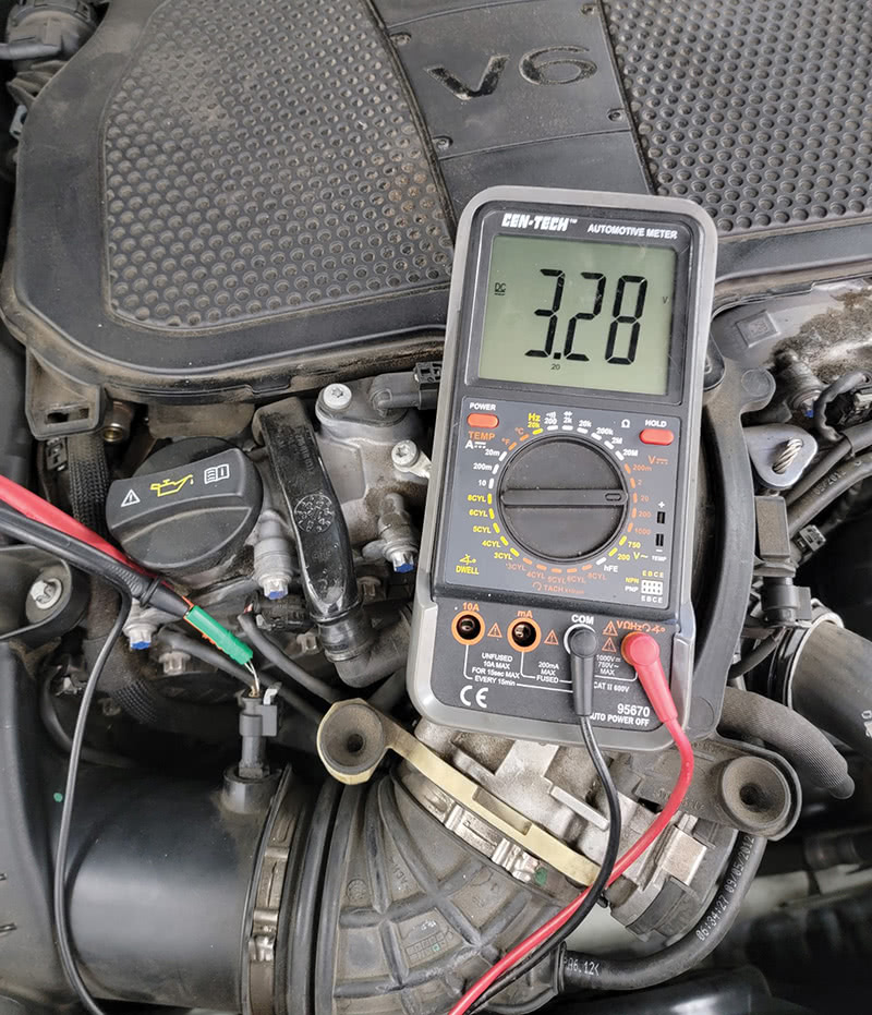
The E350 was truly doing something strange, something we hadn’t seen before. When the fault appeared, the voltage on the Intake Air Temperature (IAT) sensor suddenly jumped from its nice, steady, thermistor-like warmed-up voltage of 3.28 volts to 7.75 volts. See Figure 2.
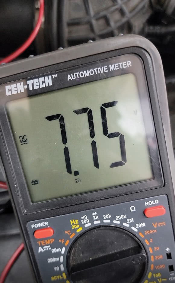
I stared at the meter and said to the tech, “I wouldn’t think what we are seeing here with our own eyes was even possible, especially from a module-bussed and regulated 5-volt reference circuit.” And as quickly as we looked back at the meter, the circuit was sitting back at 3.28 volts, happy as could be. See Figure 3.
Uh, oh. Rogue Electrons…
Since we had now captured the fault and began to (semi) understand what was happening, we began the typical visual inspection, wiggle test on harness and connectors and a few other checks and then made some diagnostic decisions. As would be normal in a case like this, we thought: Ok, simple. We’re shorting to voltage. Every time the voltage would show up, we would feverishly try to figure out where it was coming from, but to no avail. It just came… and then it went.
The worst part was that it was not entirely dependable in its time frame between faults. At times, the fault would appear, disappear and re-appear almost cyclically, other times this vehicle would sit and idle or drive around for half of the day or more, before the fault suddenly reappeared.
Sometimes these intermittents are tough. But this one was defying what should physically be allowed to happen on these circuits… Where does this 7.75 volts come from out of nowhere, the same 7.75 volts exactly, every single time, which was higher than the true voltage reading through the sensor and higher than sensor supply voltage to boot.
We decided to be prudent in our diagnostic, so we took the time to disconnect both ends of the harness at several sensors and the ME module. We loaded the wires with a #194 light bulb and checked the voltage drop on the 5-volt reference and signal wires between ME and the sensor. Both measured a drop of only about 0.01 volts, indicating that the wiring and connectors under load were functioning properly. Next, we tested each of the wires to ground and got no continuity there, as expected: The circuit is going to voltage, not to ground, but while it is all apart, it is always best to be sure!
With the wiring fully and properly checked, we decided to test the system running live with an oscilloscope to see if we could detect any anomalous electrical ‘behavior’ when the fault occurred. Once we rigged up, it was a matter of hurry up and wait. Sure enough, about 20 minutes into scope monitoring of the circuit, the 7.75 volts appears. Now, it gets interesting. As we were analyzing the ‘event,’ we noticed a strangely familiar characteristic with the waveform—a characteristic that I often see when working with radio transcievers.
The waveform we saw (Figure 4) was exactly what one would expect from charging and discharging capacitor. Bingo, this was the “ah-ha!” moment. Having seen this many times before while building and repairing vacuum tube ham radios and audio amps, the waveform’s classic signature caught my eye right away.
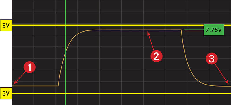
We investigated further, and sure enough, the capacitive discharge of the voltage infecting this circuit became almost cyclical at times. Strangely, the charge and discharge signature was riding on the 5-volt circuits, and when the discharge cycle occurred, voltage returned to normal on the wire. So, our best guess is that an oscillator of sorts was being set up as this fault occurred, cycling a rogue capacitor in the voltage regulation circuitry inside the ME. But no matter what went rogue inside the module, it was fairly clear that we were seeing an unwanted capacitive discharge, going from 7.75 volts back to 3.28 volts.
An oscillator is an electronic circuit, a basic building block circuit for signal processing, chip control and many other functions. There are literally thousands of oscillator type circuits happily tick-tock-ing away inside of each of our on-board modules.
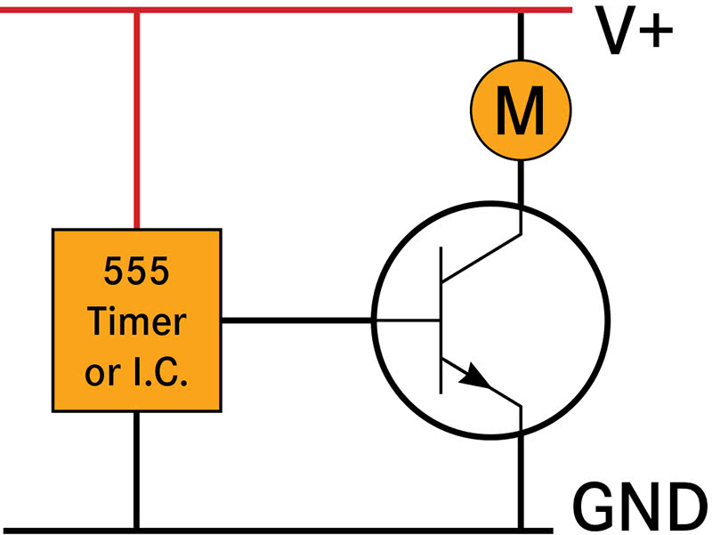
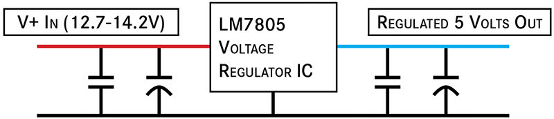
The voltage regulators that supply bussed and regulated voltage (for the 5-volt reference circuits) are semiconductor devices (IC chips) combined with other components like capacitors and resistors to drop, filter and regulate voltage.
But how do these key electronics components work, and why do we need to understand this? Well, you really don’t need to know these characteristics to get the car fixed eventually—you can always bring out the parts cannon. Nonetheless, if you do study electrical behavior characteristics, you would likely have a far better shot at solving this particular problem and many others, as compared to if you did not.
We acknowledged, however, that the technicians previously working on this car were (A) likely never trained specifically on signature analysis of electronic components, and also, (B) whomever was working on this vehicle would likely have stumbled on the fix by eventually replacing the ME, which in this case could have fixed the car. But here’s the thing; we didn’t NEED to replace the ME module.
Why, you ask? Great question! All great diagnostics have some great questions built into them. Here was our great question, that provided a significant clue:
Mrs. Customer, could you please tell us if you remember when this concern started and what could have possibly precipitated this issue? Did the Check Engine Light just appear out of the blue while you were driving down the road, or was this something that happened one day when you started the car… could you help us with any clues?
Answer: “Sure, I know right when this started. One morning, the car wouldn’t start. It had a weak battery. The tow guy came and tried to jump start my car. After some fiddling, he was able to get it started, but the light came on while it was warming up and we decided to have him tow it in, just to be safe. That’s how this all started.”
“You told this story to the three facilities trying to sort this out for you?”
“Yes sir,” she says. “All three of them.”
Huh.
We checked the RO on the car, here’s what the labor line said: Check engine light on, check and advise.
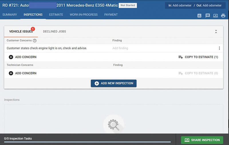
That’s it. Nothing else. Now, let’s think about this for a minute. Is it any wonder that this particular tech was having issues solving this car? The electrical problem we’ve locked on to here is no joke to figure out, but three different service advisors at three different shops, and none of them were able to convey this customer’s important clue to the technician? The clue the customer provided us changed our diagnostic direction immediately upon hearing it, and in the end we had the fault isolated and corrected about 30 minutes later.
Here’s what we did with this human intelligence:
- After hearing that the problem started with the “tow guy” and a jump start situation, we began to wonder if maybe he jump-started the car backward for a “sec” whilst trying to jump it. Mistakes do get made sometimes.
- The other thought that crossed our minds was that maybe this was occurring because the key was on when he attached the jumper cables. He may have sparked and fumbled with the power enough with the key on, maybe the processor took some transient surges it didn’t like and took some damage that way, specifically to the regulated voltage section of the ME module.
The waveform spoke to us. This was surely a capacitor charging and then draining itself cyclically after charging to 7.75 volts that shouldn’t have been there. Finally, we verified the temp sensors were reading correctly when the circuits were working properly.
Engine Coolant Values Chart
| 10°C | Ω | 3700 (±5%) | 4925.4 (±5%) |
| 10°C | V | 3.9 (±5%) | 3.85 (±0.06V) |
| 20°C | Ω | 2500 (±5%) | 3086.6 (±5%) |
| 20°C | V | 3.5 (±5%) | 3.39 (±0.07V) |
| 30°C | Ω | 1700 (±5%) | 1998.1 (±5%) |
| 30°C | V | 3.1 (±5%) | 2.88 (±0.07V) |
| 40°C | Ω | 1170 (±5%) | 1327.1 (±4%) |
| 40°C | V | 2.7 (±5%) | 2.37 (±0.07V) |
| 50°C | Ω | 830 (±5%) | 902.3 (±4%) |
| 50°C | V | 2.3 (±5%) | 1.9 (±0.06V) |
| 60°C | Ω | 600 (±5%) | 626.7 (±4%) |
| 60°C | V | 1.9 (±5%) | 1.49 (±0.05V) |
| 70°C | Ω | 435 (±5%) | 443.8 (±3%) |
| 70°C | V | 1.5 (±5%) | 1.16 (±0.04V) |
| 80°C | Ω | 325 (±5%) | 319.9 (±3%) |
| 80°C | V | 1.2 (±5%) | 0.894 (±0.031V) |
| 90°C | Ω | 245 (±5%) | 234.4 (±3%) |
| 90°C | V | 1.0 (±5%) | 0.688 (±0.024V) |
Air Intake Values Chart
| 10°C | Ω | 9670 (±5%) | 9470.2 (±4.5%) |
| 10°C | V | 3.2 (±5%) | 4.209 (±0.036V) |
| 20°C | Ω | 6060 (±5%) | 5869.2 (±4.5%) |
| 20°C | V | 2.6 (±5%) | 3.836 (±0.045V) |
| 30°C | Ω | 3900 (±5%) | 3750.2 (±4.5%) |
| 30°C | V | 2.1 (±5%) | 3.391 (±0.053V) |
| 40°C | Ω | 2600 (±5%) | 2469.6 (±4%) |
| 40°C | V | 1.6 (±5%) | 2.906 (±0.052V) |
| 50°C | Ω | 1760 (±5%) | 1674 (±3.5%) |
| 50°C | V | 1.2 (±5%) | 2.423 (±0.046V) |
| 60°C | Ω | 1220 (±5%) | 1164 (±3.5%) |
| 60°C | V | 0.9 (±5%) | 1.977 (±0.043V) |
| 70°C | Ω | 860 (±5%) | 827.1 (±3.5%) |
| 70°C | V | 0.7 (±5%) | 1.586 (±0.041V) |
| 80°C | Ω | 620 (±5%) | 599.2 (±3.5%) |
| 80°C | V | 0.5 (±5%) | 1.259 (±0.035V) |
| 90°C | Ω | 245 (±5%) | 441.2 (±3.5%) |
| 90°C | V | 0.2 (±5%) | 0.993 (±0.029V) |
The diagnostic decision? After studying the fault occurring on the lab scope and watching the behavior of the circuit, we decided to perform a global battery reset on the car. Our theory was that the car was jumpstarted backwards, and rogue voltage was being stored in a capacitor. Somehow within the electronics, apparently involving the voltage regulator circuit for the 5-volt reference voltage, the faulting component provided a pathway to our circuit.
We disconnected the cables, shorted them together and went home for the night. The next morning, we reconnected the battery, checked for the presence of DTCs and took the car on a test drive. The fault never returned.
When I say never, I mean this case occurred almost exactly one full year ago, and in preparation for this article, I personally called the shop owner to see if “Mrs. Customer” had been back with her weird E350 problem. “No sir,” he says, “and I can’t thank you guys enough either. She has become a great customer for us because she trusts us and believes we fixed her car when others couldn’t.”
We will never know exactly which component in the ME control unit was responsible, or the exact failure mechanism. Our speculation is really an educated guess, but this is very different from an uneducated guess: That waveform’s shape really was saying something—and quite loudly at that.
This case shows the need to focus on the basics of electrical behavior and constantly hone our physical testing skills. Getting better with MASINT skills and fundamentals will advance your diagnostic abilities far beyond those in our field that choose not to study such things. Of that we are sure. The basics are important, and you never know when additional knowledge will come in handy.
Now that the ghost is gone, we have a happy Mercedes-Benz owner, a happy shop owner and technician that learned some things along the way. Most importantly, where others had failed, he stuck with it until the end.
Now THAT is a great diagnostic day for all.


Excellent Article and many truths about where our industry is and the demands of current and future technicians.