


Advanced materials and technology play a leading role in Volvo lighting systems.
Through the years Volvo’s lighting systems have changed significantly. From the basic bulb lights, front and rear, to halogen, xenon, and now LED. In this article we will go over the different lights, how they work, and the different functions in the system.
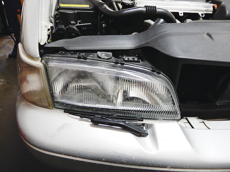
Here we have an S70 with halogen front lights with glass lenses. This system of lighting was a pretty simple system. The bulbs were pretty easy to get to and did not experience frequent failures. The biggest problem with this model was the connector at the headlight becoming very hot and melting, burning the connector and harness. Cutting the wires back and replacing wires and connectors is a common repair with this model.
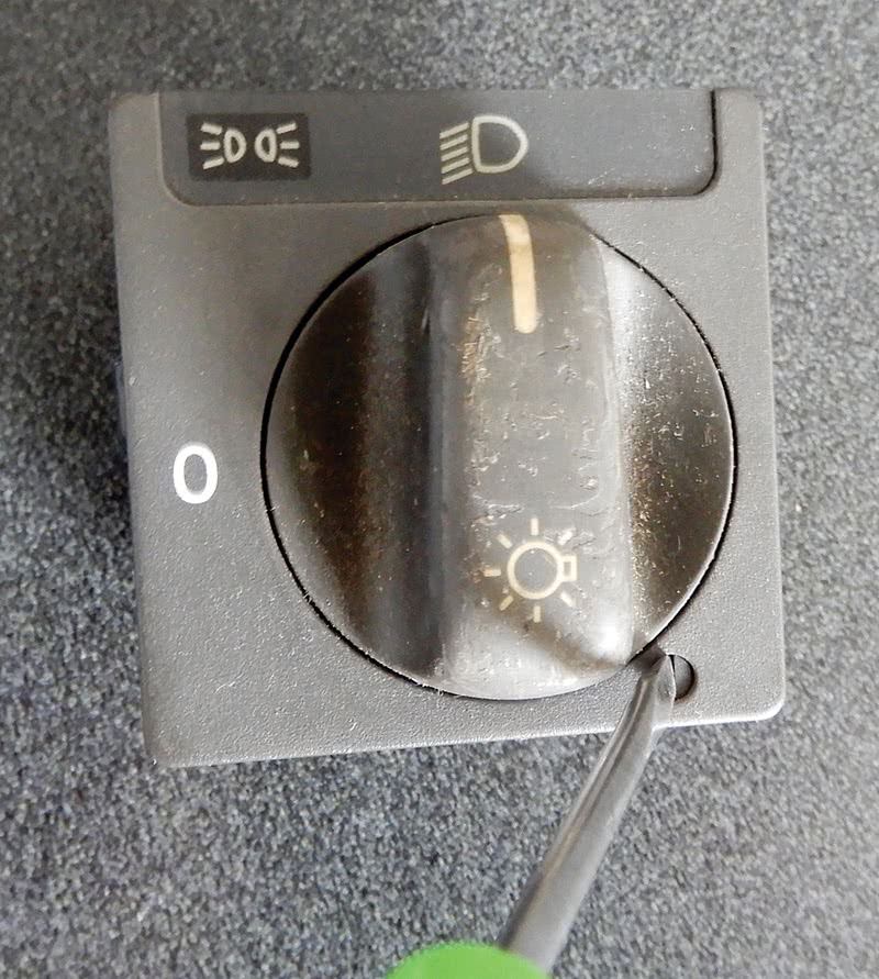
The headlight switch on the S70 has an adjustment so you can turn off daytime running lights. This way the lights only work when you turn the switch to the On position.
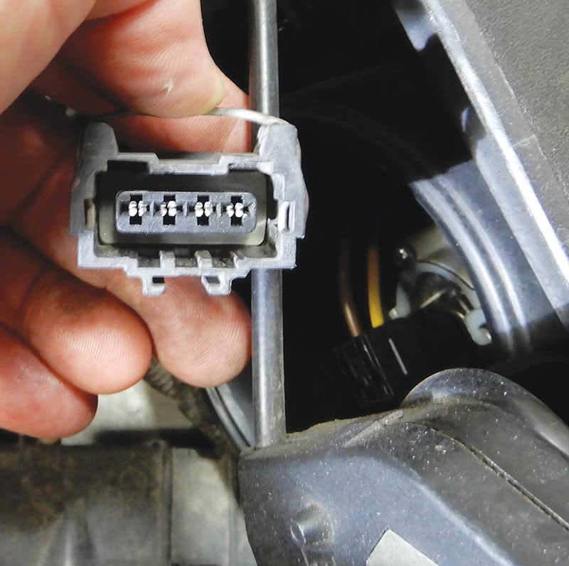
Another common problem on these S70s was corrosion at the electrical plug at the headlight assembly. Cleaning the plug and headlight receptacle with electric spray cleaner and adding dielectric grease and plugging it back in would usually take care of this problem.
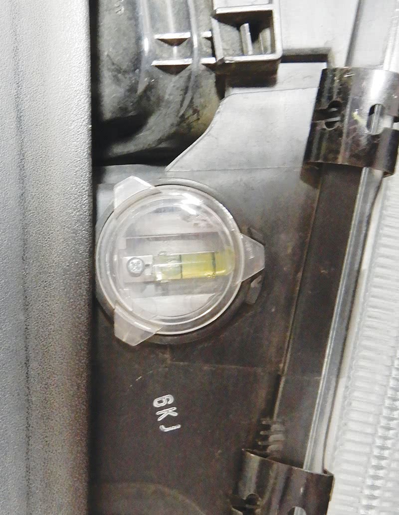
Leveling and adjusting the headlight and beam is pretty straightforward on this model. There are two adjustments for moving the beam up and down and also side to side. There is also a small bubble level on top of these headlights to help with adjustment.
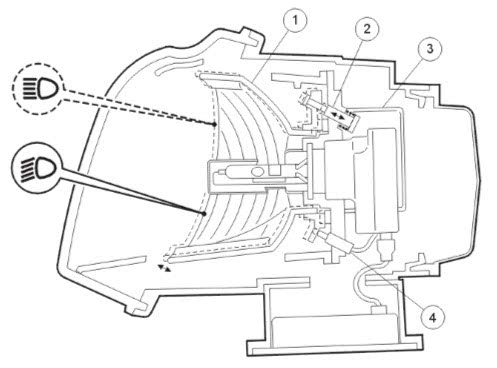
In early 2003, Volvo introduced Gas Discharged Lamps (GDLs). These lamps were brighter and made nighttime driving a little easier. The Bi-Xenon or GDL designs use a gas discharge technology and the headlight system has moving reflectors for more ability to see at night.
The high and low beam lights are intergraded into one bulb. When using a signal bulb for both high and low beams, the headlights are equipped with an automatic leveling system.
The bulb itself consists of a discharge pipe surrounded by glass which filters out damaging UV radiation. There are a number of chemical compounds in the glass tube, including xenon gas.
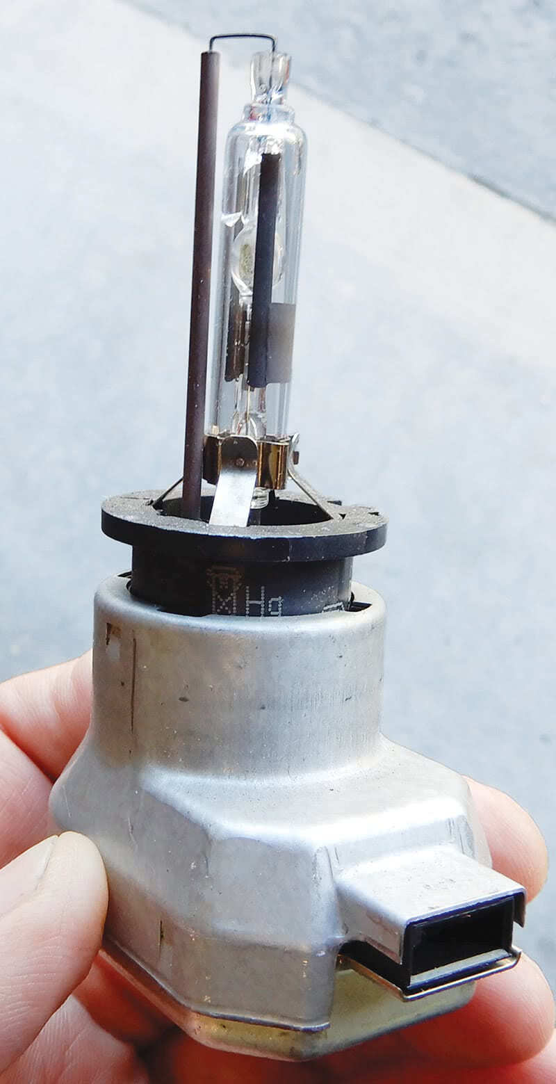
An electric discharge between two tungsten electrodes creates the arc in the light itself. The D2R bulb is designed for the special reflector system. The power consumption is 35 watts, and the bulb is less susceptible to bumps and vibration.
The difference between halogen and xenon is that xenon has a higher color temperature which gives a whiter light. This helps with the reflection of road signs and has a lower power consumption. The high and low beam bulb having the same color light is an advantage in the Bi-Xenon system. The human eye finds this easier to react to between changes.
Each headlight in the Bi-Xenon setup also has a ballast that is positioned on the bottom side of the headlight assembly. The ballast works as a voltage regulator and generates alternating current. The ballast basically lights the bulb and controls the light during operation.
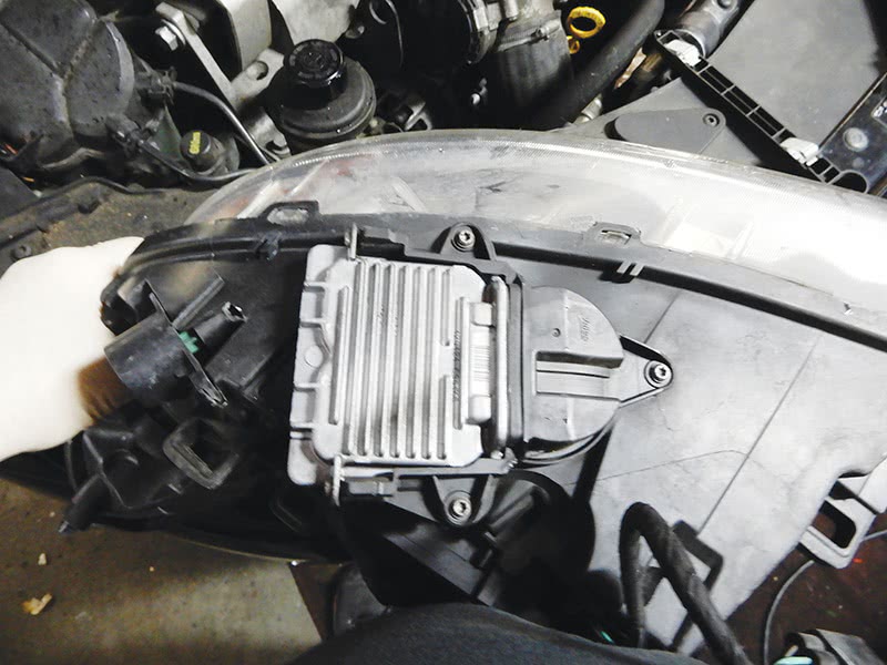
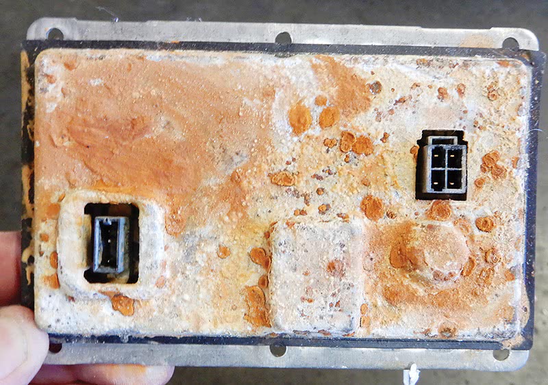
Here we have a customer with a headlight that doesn’t work. The place to start is by checking the bulb and fuse just to make sure one or the other is not bad; if so, replace either bulb or fuse. In this case both were fine. We removed the headlight to find that the headlight lens seal had failed and water was getting inside. On the bottom side of the headlight assembly, we found that the ballast was rusty and was damaged from water getting into the unit. The ballast was replaced and the headlight worked fine. Make sure to replace the seal or headlight assembly so this won’t happen again.
The voltage from the ballast transforms 12 volts DC to 1000 volts AC. High voltage is necessary to get the lamp lit. Once the headlamp is lit, the voltage is reduced to 100 volts to keep the headlamp lit.
The headlamp will not light if the voltage is 9.5 volts or less within a time span of 200 ms. If the voltage is too low during a cold startup and the headlamp does not come on, the alternator will charge the system and you will have to turn the light switch off and then on again to restart the headlamp. With the ignition on, it usually takes three seconds for the headlamp to activate.
The moving reflector inside the headlight plays a key role; there are three different segments inside the headlamp. The reflectors are adjustable and can move depending on whether the position of the light is on high or low beam. The bulb never moves and the headlight lens is clear. The movement of the reflectors determines the position of the headlamp, high or low.
The Four-C system (Continuously Controlled Chassis Concept) automatic level control is different, using sensors to control the angle of the vehicle relative to the surface it rides on. The angle is measured from the vehicle leaning and is dependent on weight distribution.
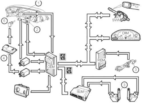
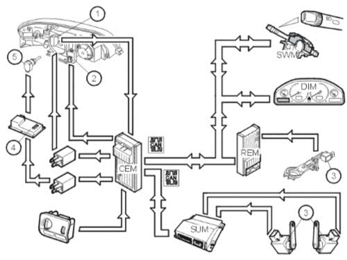
The sensors are mounted on the control arms and are mounted differently depending on whether vehicle is AWD or just FWD. The CEM (Central Electronic Module) controls the motors for the headlamp range adjustment. The REM (Rear Electronic Module) reads an analog signal (0.5-4.5 volts) from the position sensor and converts it to an angle value (plus or minus 35 degrees). Then this information is transmitted to the CEM.
The two sensors on the rear control arms read off the angle of the vehicle relative to the position it is sitting on the pavement. The angle is a measurement of how much the vehicle is leaning and is dependent on the weight distribution. The SUM (SUspension Module) reads the signals from the sensors and converts them to an angle value.
The value is transmitted through the CAN (Control Area Network) to the CEM (Central Electronic Module), and then the CEM uses the information to control the motors for the headlamp’s adjustment.
Under about 2 1/2 mph with ignition on, the position sensor is read off and the headlamp range is adjusted in the headlamps. Over that speed, during driving, the headlamps change depending on the angle of the vehicle. Control is dependent on the time for the system not to react to short term changes such as uneven road surfaces.
When replacing rear suspension parts such as sensors, bushings, shock absorbers, springs or axles, the system must be calibrated through VIDA. Calibration can be done through VIDA, Diagnostics/Vehicle Communication, REM (Rear Electronic Module).
Automatic Headlamp Leveling and Active Headlamps 2012 S60
On the 2012 S60 Volvo, the functions of the automatic leveling and active headlamps are controlled by the CEM (Central Electronic Module). There is a separate control module that controls the automatic headlamp leveling and active headlamp functions.
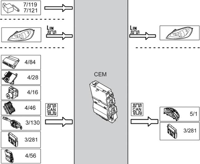
Here are the input signals to, and the output signals from, the CEM. Here we will divide the signals from input signals to output signals, serial communication and CAN communication. We will also show the Volvo component designation number.
Input Signals:
Directly Connected
- Position Sensor (7/119,7/121)
via serial communication:
- Left Headlight Control Unit (LHCU)
- Right Headlight Control Unit (RHCU)
via Controller Area Network (CAN) Communication:
- Suspension Module (SUM) (4/84)
- Transmission Control Module (TCM) (4/28)
- Brake Control Module (BCM) (4/16)
- Engine Control Module (ECM) (4/46)
- Steering wheel Angle Sensor Module (SAS) (3/130)
- Infotainment Control Module (ICM) (3/281)
Output signals:
Directly connected
via serial communication:
- Left Headlamp Control Unit (LHCU)
- Right Headlamp Control Unit (RHCU)
via Controller Area Network (CAN) communication:
- Driver Information Module (DIM) (5/1)
- Infotainment Control Module (ICM) (3/281)
Headlight System Bi-Xenon Model 2012
The Bi-Xenon headlight system is based on gas discharge technology with reflectors that are moveable inside the headlamps. Like the earlier models, the Bi-Xenon lights are quite alike, as far as bulbs, position sensors and leveling systems go.
The position sensors have three wires and are directly connected to the CEM. Two wire connectors are ground and power supply and the other is used for signals for vehicle angle. When the ignition is switched on, the level control becomes active and the position sensors are used to calculate the average vehicle angle. At about 2.5 mph, the dynamic level control is activated. As speed increases or decreases, the system will make its corrections. Darkness is required in addition to speed controlled and angle of the vehicle.
Like the earlier models, calibration is needed and saved in the CEM when replacing position sensors or a control module. Calibrating the system can be done through VIDA, Diagnostics/Vehicle Communication.
Four-C (Continuously Controlled Chassis Concept) uses the signal from the suspension module. Diagnosing the position sensors can be done through VIDA.
2010 XC 90 Headlight Control Module
The headlight control module on this Volvo model communicates with directly connected components and other control modules via CAN. The control module is located under the driver’s seat, so if you need to replace the control module, the seat will need to be removed.
The control module checks input and output signals, as well as activation for components using an integrated diagnostic system. If a fault occurs, the control module will set a diagnostic trouble code. If a diagnostic trouble code does register, a number of values that were frozen when the fault occurred are stored.
Depending on how severe the fault is, some functions might not work correctly. The driver’s information module will display information text, and the LED in the active headlight button will flash. The faults and frozen values can be read through VIDA for diagnosing the fault.
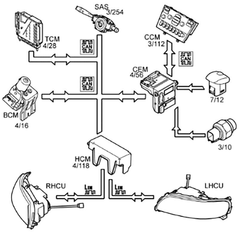
The headlight control module (HCM) (4/118) needs information from the vehicle’s speed, the current gear the vehicle is in, and light conditions to activate the active headlight functions.
The headlight control module receives information from the following control modules:
- Brake Control Module (BCM) (4/16) for vehicle speed
- Transmission Control Module (TCM) (4/28) for current gear the vehicle is in with automatic transmission
- Central Electronic Module (CEM) (4/56) from the reversing light switch with manual transmission and also information from the twilight sensor (7/12)
When the ignition switch is turned on, the headlight control module is activated. To turn the light beam off, the following conditions must be met.
- The vehicle must be moving at a greater speed than 2.2 mph.
- The vehicle must not engage reverse gear.
- And no daylight conditions.
The switch on the Climate Control Module (CCM) (3/112) for the active headlight function can be used to disable or enable the function.
When the active headlight function is turned on, the headlight control module receives continuous information on speed and steering angle. The brake control module sends the message for the speed of the vehicle, and the steering angle sensor (3/254) sends information on the steering angle of the vehicle. This information then enables headlight control module to calculate the current turnout of the light beam.
Software can be added to headlight control module to change the active headlight function to adapt to either driving on the right side of the road or left side of the road, depending on the country you drive in. To change the settings, hold the active headlight switch on the climate control module down for five seconds. When the settings have been changed, a message will appear in the driver’s information module to let you know if it’s for right-hand or left-hand traffic.
When driving straight forward, the light beam is turned so it does not blind oncoming traffic. The light beam will also be turned out in the direction when cornering, but not as much. The light beam is also aimed down slightly so as not to blind oncoming traffic.
Diagnostic Functions
Volvo diagnostics are built into the control module to continuously monitor the functions of the system, in addition to monitoring the input and output signals.
If a fault occurs, a diagnostic trouble code will be stored in the control module. A fault that occurs during a most recent driving cycle is a permanent fault. Other faults are intermittent faults and could be harder to locate.
Using VIDA, you can read all faults and erase using this function. VIDA can be used to monitor the input and output signals of the control module in Vehicle Communications. Also in VIDA, you can activate components to check if they are working correctly.
With VIDA, you can read off the control module hardware part number, hardware serial number, software part number and diagnostic software part number.
The Volvo lighting system can be very challenging at times; using VIDA can give you the information you need to diagnose, download software and understand the complete function of the system.


Beautiful article!
Thank you. We’re glad to see you enjoyed it and hope it benefits your business.