


In the late 1990s the Volvo 850 arrived with manual MCC and ECC electronic climate control systems.
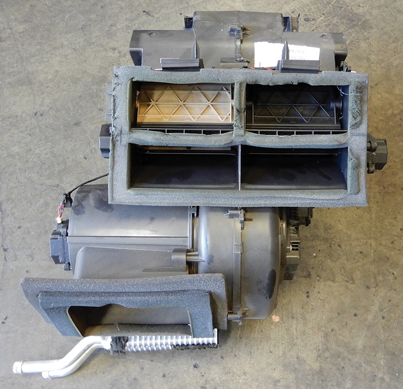
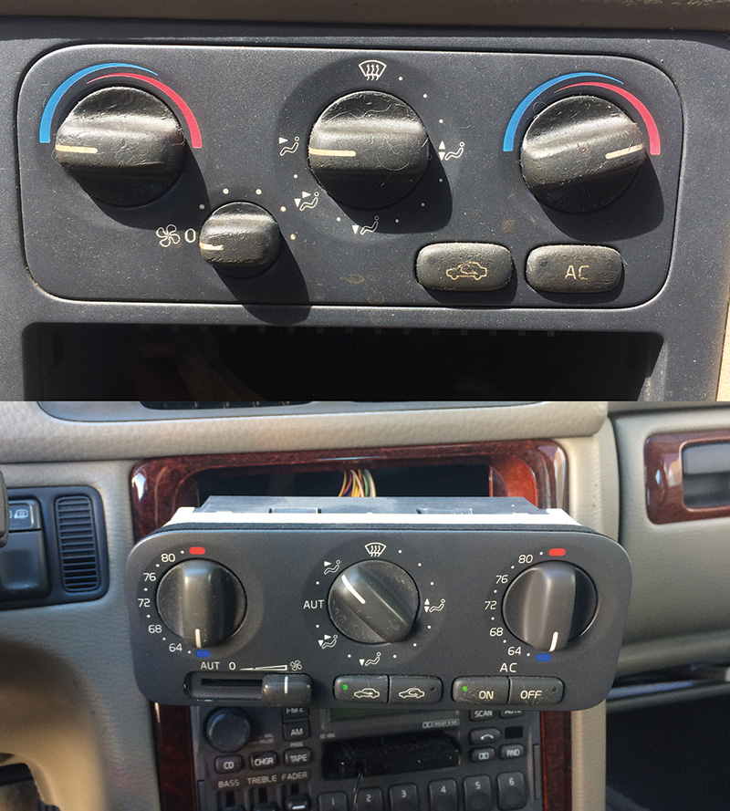
In the late 1990s the Volvo 850 arrived with Manual MCC and ECC electronic climate control systems. Air conditioning and heat both would share a single heater box with manual control cables that connected to flaps for distribution of air for floor, defrost, and center outlet distribution. Electronic controls would be wired to small motors that actuate the flaps. Inside the box is a heater core and an A/C evaporator. Air conditioning electrically supported a compressor that was run by a fan belt. A button was located on the control panel to support the A/C system. Both passenger and driver have temperature controls for each side. A recirculation button is provided to shut off outside air.
The MCC manual controlled system used a fan resistor for adjusting speed control, along with a max speed relay and an A/C relay.
ECC used damper motors for adjusting air control and temperature. A power stage is used for blower speed and an A/C relay is used for powering up the A/C compressor.
Temperature controlled air is drawn in from outside or inside depending on the recirculation position. On the MCC cable controlled system both passenger and driver could each have their own temperature settings. ECC had a damper motor on both sides to control temperature depending on settings. The settings determine how much air flows through the heater.
ECC damper motors controlled the amount of air flow depending on various settings. Five damper motors controlled the system, with two temperature motors, one on each side of the heater box. Air distribution could be adjusted for windshield defroster, side defroster, center ventilation, side ventilation, rear floor, and front floor.
Volvo air conditioning systems control air temperature in vehicles to be at a comfortable level and to dehumidify the air coming into the vehicle. The air conditioning system is filled with refrigerant and functions like a refrigerator.
Dehumidified air feels cooler. When air comes into vehicle and passes through the evaporator, the humidity in the air condenses on the evaporator. The water that accumulates is drained through a tube to the outside of the vehicle. Often times customers will think they have a water leak but this is quite normal.
Main components in air conditioning system include:
- Evaporator
- Drier or accumulator
- Condenser
- Compressor
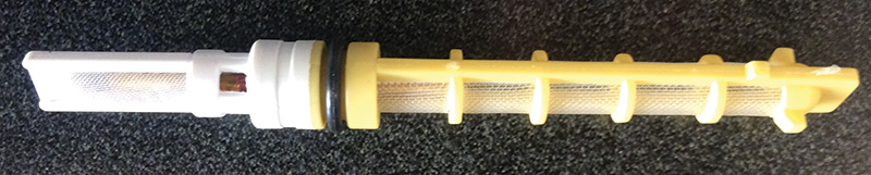
- Orifice
The system has a high and low side pressure that is separated in the compressor and the orifice. The air conditioning system will not work if outside temperature is below 42 degrees F. The compressor cannot engage at low pressure due to the temperature outside being too cool.
Let’s talk about the components in the air conditioning system. The evaporator is located on the low side of the system. Heat is transferred from warm air to the cold refrigerant. The refrigerant boils and converts to a gas state. The blower motor will increase air flow through evaporator.
The drier, or accumulator, could be located on either the high or low side depending on the system. The drier absorbs moisture and water in the system.
The condenser is located on the high side. The heat is transferred from high pressure vaporized refrigerant to cooler outside air, then condenses back to liquid form. The engine cooling fan is located near the condenser to increase the air flow to transfer heat from the refrigerant to outside air.
The A/C compressor sucks low pressure vaporized refrigerant from the evaporator. Refrigerant is compressed into high pressure and then the warm gases are pushed into the condenser.
The orifice separates the system’s high pressure side from the low pressure side and controls the amount of refrigerant that flows into the evaporator. It is located in the evaporator inlet.
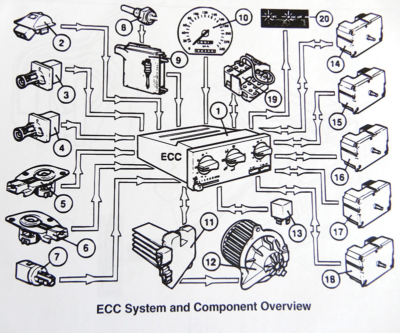
ECC System and Components | |
| The ECC control unit (1) receives information from the various components in the system. | Speedometer (10) |
| Solar sensor (2) | Power stage (11) |
| Driver’s duct side temp. sensor (3) | Blower motor (12) |
| Passenger’s duct side temp. sensor (4) | A/C relay (13) |
| Driver’s side interior temp. sensor (5) | Damper motors floor and defrost (14 and 15) |
| Passenger’s side interior temp. sensor (6) | Temp. control both sides (16 and 17) |
| Outside temp. sensor (7) | Recirculation damper motor (18) |
| ECT/sensor, engine coolant temp. (8) | Data link for diagnosing (19) |
| ECM/engine control module (9) | Detected fault blinking on control module (20) |
With this system it may be set for automatic or manual. Controlling the temperature, blower speed and air distribution make this system quite comfortable for both driver and passenger.
Diagnosing Climate Control System 850 Volvo
The ECC control module is capable of detecting faults and storing codes.
When ignition is switched on, the A/C off and Recirculation buttons flash a light for 20 seconds if there is an issue in the system.
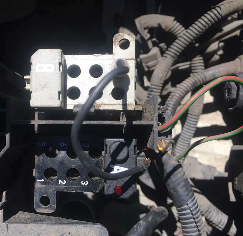
Test unit (9813190) and adapter (9813194) are used for diagnosis or self diagnosis.
Diagnostic units A and B are side by side with a connecting cable to insert in position depending on which control unit you are communicating with. In this case the connector cable will be inserted into B side number one for climate control. Turn the ignition to On position, push button and release; light will flash three digits then a short break and continue until all codes are read.
Fault codes | |
| 1-1-1 | No Fault Found By Diagnostic System |
| 1-2-1 | Outside Temp. Sensor Circuit Shorted To Ground |
| 1-2-2 | Outside Temp. Sensor |
| Circuit Open Or Shorted To Power | |
| 1-2-3 | Driver’s Side Temp. Sensor Circuit Shorted To Ground |
| 1-2-4 | Driver’s Side Temp. Sensor |
| Circuit Open Or Shorted To Power | |
| 1-2-5 | Pass. Side Temp. Sensor Circuit Shorted To Ground |
| 1-2-6 | Pass. Side Temp. Sensor |
| Circuit Open Or Shorted To Power | |
| 1-3-1 | Driver’s Side Duct Temp. Sensor Shorted To Ground |
| 1-3-2 | Driver’s Side Duct Temp. Sensor |
| Circuit Open Or Shorted To Power | |
| 1-3-3 | Pass. Side Duct Temp. Sensor Shorted To Ground |
| 1-3-4 | Pass. Side Duct Temp. Sensor |
| Circuit Open Or Shorted To Power | |
| 1-3-5 | No Engine Temp. Frequency Signal |
| 1-4-1 | Driver’s Side Temp. Switch Faulty Control Signal |
| 1-4-3 | Pass. Side Temp. Switch Faulty Control Signal |
| 1-4-5 | Air Distribution Switch Faulty Control Signal |
| 1-5-1 | Fan Speed Sensor Control Signal Missing Or Too High |
| 1-5-2 | Fan Speed Sensor Control Signal Shorted to Ground |
| 2-1-1 | Driver’s Side Damper Motor Position Sensor |
| Circuit Open Or Shorted To Power | |
| 2-1-2 | Driver’s Side Damper Motor Position Sensor |
| Shorted To Ground | |
| 2-2-1 | Pass. Side Damper Motor Position Sensor |
| Circuit Open Or Shorted To Power | |
| 2-2-2 | Pass. Side Damper Motor Position Sensor |
| Shorted To Ground | |
| 2-3-1 | Ventilation Damper Motor Position Sensor |
| Circuit Open Or Shorted To Power | |
| 2-3-2 | Ventilation Damper Motor Position Sensor |
| Shorted To Ground | |
| 2-3-3 | Floor/Defrost Damper Motor Position Sensor |
| Circuit Open Or Short To Power | |
| 2-3-4 | Floor/Defrost Damper Motor Position Sensor |
| Shorted To Ground | |
| 2-3-5 | Recirculation Damper Motor Position Sensor |
| Circuit Open Or Short To Power | |
| 2-3-6 | Recirculation Damper Motor Position |
| Sensor Shorted To Ground | |
| 3-1-1 | Driver’s Side Damper Motor Shorted To Ground Or Power |
| 3-1-2 | Pass. Side Damper Motor Shorted To Ground Or Power |
| 3-1-3 | Ventilation Damper Motor Shorted To Ground Or Power |
| 3-1-4 | Floor/Defrost Damper Motor Shorted To Ground Or Power |
| 3-1-5 | Recirculation Damper Motor Shorted To Ground Or Power |
| 3-2-1 | Driver’s Side Damper Motor Active Too Long |
| 3-2-2 | Pass. Side Damper Motor Active Too Long |
| 3-2-3 | Ventilation Damper Motor Active Too Long |
| 3-2-4 | Floor/Defrost Damper Motor Active Too Long |
| 3-2-5 | Recirculation Damper Motor Active Too Long |
| 4-1-1 | Pass. Compartment Fan Over Current or Seized Fan |
| 4-1-2 | Driver’s Side Temp. Sensor |
| Intake Fan Shorted To Ground | |
| 4-1-3 | Driver’s Side Temp. Sensor |
| Intake Fan, No Control Voltage | |
| 4-1-4 | Driver’s Side Temp. Sensor Intake Fan Seized |
| 4-1-5 | Pass. Side Temp. Sensor Intake Fan Shorted To Ground |
| 4-1-6 | Pass. Side Temp. Sensor Intake Fan, No Control Voltage |
| 4-1-7 | Pass. Side Temp. Sensor Intake Fan Seized |
| 4-1-8 | No Control Signal To ECC Power Stage |
| 4-1-9 | ECC Power Stage Emitting Faulty Diagnostic Signal |
| 4-2-0 | ECC Control Module Fault, Program Memory |
| 5-1-1 | Self-Adjustment Of Damper Motor |
| Limit Positions Not Carried Out | |
ERASING CODES
- All codes must be displayed at least once before they can be erased. To erase codes, ensure selector cable is connected to terminal No. 1 of diagnostic unit B. Press and hold the diagnostic button for at least 5 seconds. The LED should illuminate 3 seconds after the button is released.
- Press and hold the diagnostic button for a minimum of 5 seconds more. When the button is released, the LED should go out. Ensure codes have been erased by pressing the diagnostic button once. If display shows 1-1-1, codes have been erased/cleared. If a DTC will not erase/clear, perform that particular code’s diagnosis again.
Diagnosis can be accomplished with the right tools and knowledge. Replacing a damper motor or recirculation motor on a 1996 850, for example, can be achieved by removing the passenger kick panel on bottom and removing the glove compartment. This will expose the blower motor, and above it is the recirculation motor. Start the vehicle and push the recirculation button and watch if the controls for the motor are moving and, if so, by how much. Remove the outside windshield wipers on both sides and the plastic cowling. Remove the cabin filter and flap so you can see if the recirculation flap can be seen open or closed. Remove the damper motor inside the cabin and replace with a Volvo Genuine part. Making sure the flap is closed to outside air when connecting.
When replacing the damper motor, any resetting of the end positions must be performed with a Volvo hand held scan tool or in position four on data link.
S/C/V70
Once the S/C/V70s came along everything was electronic and no cables were used. ECC has four damper motors to control air distribution, temperature left side and right side, and recirculation utilizing a separate A/C switch button and recirculation button, along with a blower motor speed adjustment button.
Sensors (temperature controlled sensors) calculate the temperature inside the cabin as well as outside ambient temperature. Adjustment settings are inside the cabin at the climate control face plate. This system includes self adjusting damper motors through hand-held VST (Volvo Scan Tool).
Functions on the face plate ECC and MCC include temperature dials for both driver and passenger. A function selector in the middle provides for desired air flow via upper, lower, or in-panel vents (middle).
The air conditioning system should be serviced and checked once a year. A drain tube from the heater box to under the vehicle should be checked to make sure it’s not plugged. Running the vehicle with the A/C on, look for condensation dripping out under and around the passenger compartment. Refrigerant for this system is R134a and should never be mixed with any other type of refrigerant. The system is a sealed system and any type of leakage should be dealt with immediately. A system left open will accumulate moisture and dirt and not work as efficiently.
The air conditioning is disengaged when blower control is at zero and the speed of the vehicle is under 20 mph. The air conditioning system will only operate at temperatures above 32 degrees F. The recirculation button can close off outside air and help cool quicker and can be used to shut out exhaust gases or any outside air pollution. If the panel vents are open, a certain amount of air will always flow through, regardless of the position the function dial is in. To increase the flow of air to either the floor or the windows, close the panel vents and open the outer vents.
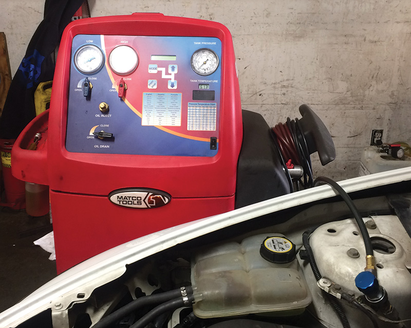
When working on the A/C system, replacing hoses or any component, cap open ends until a new hose or component is replaced. It’s always a good idea to replace the drier or accumulator any time there is a major leak in the system. The system should be evacuated for a period of 20 minutes or longer and then checked for leaks. Make sure to add the correct amount of refrigerant and check to see how much and what kind of refrigerant oil is needed. Adding dye to the system will help in detecting future leaks. Make sure to test drive the vehicle to ensure the temperatures are right and that the system is cold enough.
If there are faults in the ECC system, the Recirculation On and A/C Off lights will flash for approximately 20 seconds. If this flashing happens the next time the system is switched on, the climate control unit should be checked. This can be done with Volvo scan tool. If the control unit detects an issue a DTC is stored.
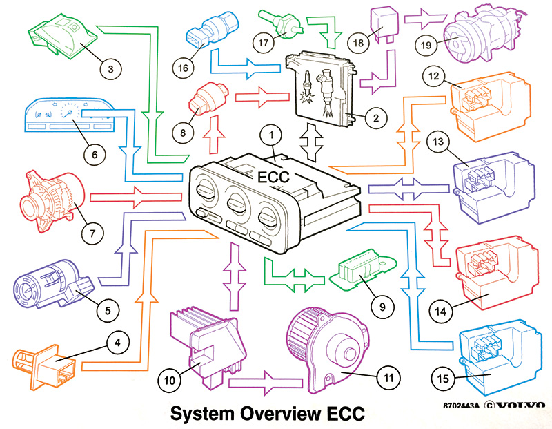
ECC System Components and Location | |
| 1 ECC control module | 11 Blower motor |
| 2 Engine management system | 12 Damper motor air distribution |
| 3 Sun sensor | 13 Damper motor temp. left side |
| 4 Outside temp. sensor | 14 Damper motor temp. right side |
| 5 Interior temp. sensor | 15 Damper motor recirculation |
| 6 Speedometer | 16 Pressure sensor |
| 7 Alternator | 17 ECT sensor |
| 8 Low pressure switch | 18 A/C relay |
| 9 Data link connector | 19 A/C compressor |
| 10 Power stage | |
When replacing the damper motor or control unit, self adjusting will have to be initiated. Activating self adjustment can happen two ways. One, with a Volvo hand held tool, or driving vehicle above 20 mph for at least 15 seconds, during which the A/C LED flashes green. If self adjusting fails and the orange LED flashes, a DTC is stored and the system must be checked again.
The MCC system has fewer components with only two damper motors, one for recirculation and one for air distribution. Cables control temperature settings. Here is a view of those components.
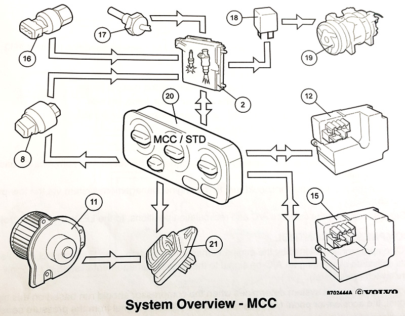
MCC System Components and Location | |
| 2 Engine management system | 17 ECT sensor |
| 8 Low pressure switch | 18 A/C relay |
| 11 Blower motor | 19 A/C compressor |
| 12 Damper motor air distribution | 20 MCC control module |
| 15 Damper motor recirculation | 21 Fan speed resistor |
| 16 Pressure sensor | |
Diagnostics in this system are much simpler than with the ECC system and DTCs are obtained through a flashing signal at the control module. DTCs can be erased and damper motor self adjustment can be performed.
Here’s how to fix a blower motor not working on a V70 or S70. You will need to remove the passenger kick panel and the glove compartment. The blower motor is now exposed and the power and ground wires can be seen. Check to see if there is power and ground with a volt meter. If power is there and the motor doesn’t run, then the blower motor is bad.
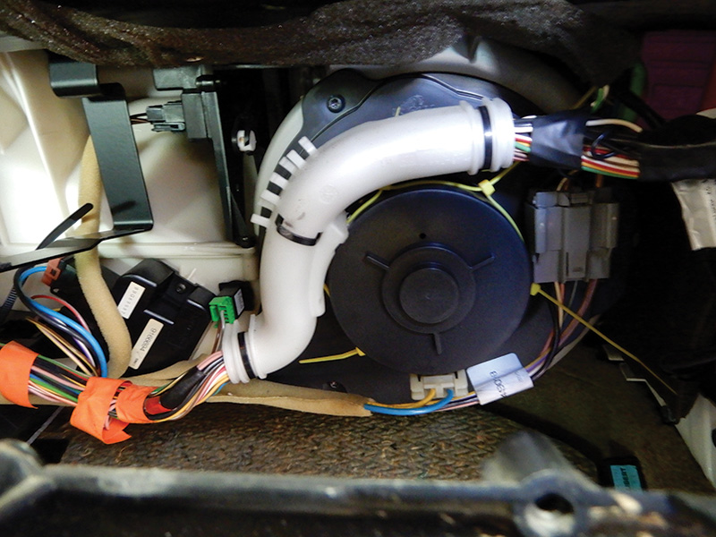
Remove all wire connections. Remove the screws around the unit and remove the motor. Installation is performed in reverse order. Now the blower motor should work properly. Adjust blower motor speeds from low to high to make sure all settings work properly.
If by some chance the blower motor doesn’t work in all positions, check the power stage or resistor. The glove compartment needs to be removed to access the motor. Use a volt meter connected at the power stage to control power, and connect the other lead to ground. Start at low speed on the control panel. Voltage will be low and increase as control goes to high. If at any time voltage is lost or doesn’t increase evenly, the power stage is bad and needs to be replaced.
Using the right tools and VST Volvo Scan Tool will make diagnosing and programming perfect. Always use Volvo Genuine Parts for all Volvo vehicles.
Download PDF


0 Comments