

A co-worker made a mention about a rough running 2006 Honda Accord, 2.4L DOHC 16V and 5-Speed Automatic and added the comment, “The car seemed hard to start.” Hard to start didn’t mean the battery or starter had a defect; rather, the engine speed took a short while to climb to normal. It was time for a lesson for the learning technicians.
With a well made power supply attached, the process of gathering faults was much simpler without the battery being depleted during the scan with accessories enabled for testing.
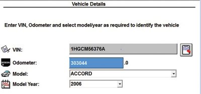
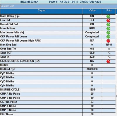
The first step was to identify the model with a complete HDS scan.
With a scan device attached, the Honda could remain alive all day long with no voltage drop outs while using a high quality power supply.
The correct industrial term is: 90 amp power converter/battery charger.
The shop term is 90 amp power supply.
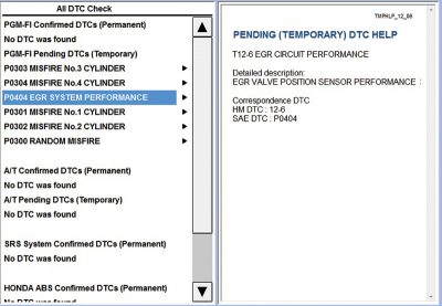
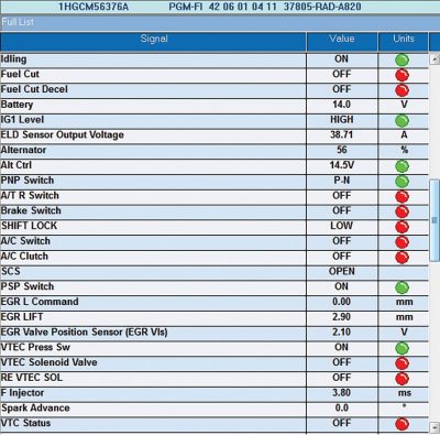
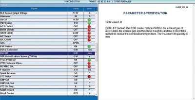
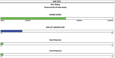
The primary indicator was how the engine seemed to start and gather rpm slower than usual. It would also idle slightly higher than normal. The data was gathered to look at the EGR at idle. It appeared and sounded like an internal vacuum leak.
That value was not what was expected and the EGR value should be 0.00 mm at idle. The next step was to test the EGR connection by disconnecting the harness at the EGR and viewing live data.
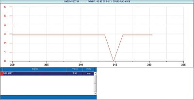
All this test does is measure the ON/OFF removal of the connection at the EGR assembly. The test proved connectivity to the engine controller.
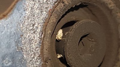
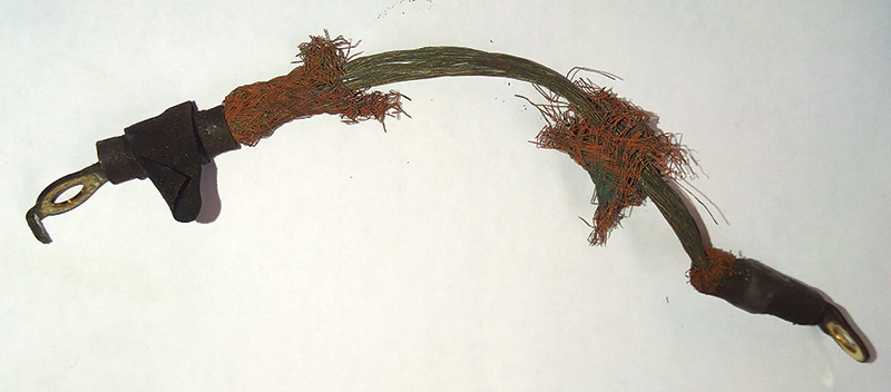
The EGR needed to be removed for an inspection.
On the opposite end, there was more debris holding the pintle open.
The solution was to gently lift the EGR with a co-worker, clean the valve with compressed air and brush off the carbon particles with a wire brush.
With reinstallation, the following images provide readings for a seated EGR at idle.
The origin of the particles is a mystery, especially the color. Do notice how those particles jammed the pintle in an open position. Consider the vacuum leak while cranking and at idle.
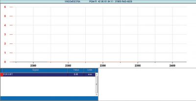
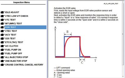
Compared to the earlier EGR connection test, this graph also indicates a seated EGR valve. HDS will also allow a running EGR test within the Inspection Menu.
Click the check mark to continue and follow the directions with HDS for the next set of steps:
- Please keep the speed below 1,500 rpm and advance to the next screen.
- HDS will request and maintain throttle between 2,500 to 3,500 rpm.
- With the test complete, the display is: Test Result System Normal.
The test passed, no faults were recorded and no misfires were recognized.
Tests with the MAF sensor; before repair 48 kPa and after repair 23 kPa.
A parasitic draw test
As an added test and while this model was in the service bay, what would a parasitic draw resemble and how quickly would this Honda enter sleep mode?
What are the most efficient and correct diagnostic steps to measure a parasitic draw? What is it that’s being measured? What does it look like?
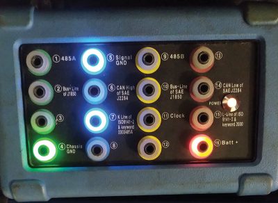
A lesson learned was to follow and search the correct information when understanding the type of communication system this Honda has. For diagnosis, the Honda uses the “K” line for diagnosis and this was noticed with a breakout box. PIN 7 during diagnosis, would flash.
Preparation is key
- Scan the vehicle and save the scan.
- Test and or repair faults within the scan.
- Delete all faults.
- Prepare the vehicle for a draw test, remove all scan/test equipment.
- Latch the hood, latch the doors that require access i.e.: internal fuse panels.
- Open and close the driver’s door. This becomes the baseline test.
- Now measure/record the parasite if there is any.
Keep it simple I
Start with the installed battery. Test it, measure it, ensure clean connections (B+ and B- and all grounds) and assure that the installed battery is correct for the model. Test the charging system for any anomalies that are related to the scan of the vehicle. It’s a hint of what may have happened in the past.
In case of dual ground cables: The negative cable
Some but not all have a single negative cable attached to a ground point. Any negative cable with more than one wire connected will not offer the correct parasite reading, even combined.
The Path of Least Resistance
Electrical energy will always take low resistance paths and will include the one with least resistance. Electrical energy will also take every other path available to it.
If that style of dual connection is evident on the negative side, there is a quick solution to connect a single cable without disturbing the original negative connection.
With an added connection, the original can be “slid off” and maintain connectivity to the vehicle with the added cable. This solution will stop the reset and lose the possibility of one or more controllers that may be the “bad actors” while measured.
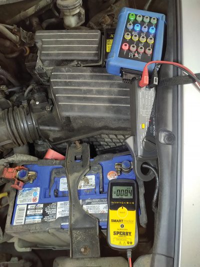
The method is drilling a hole at 1/8 diameter, with the correct depth and threading a stainless screw at approximately 0.5 cm in length to the top of the negative post (dead center). Attach an eyelet to one end of the B- and the other to a clean body ground with a purpose made cable.
| Note: On the opposite side of the engine, inspect the ground cable from the engine mount to the body. Replace if questionable. |
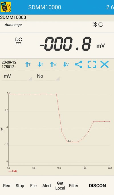
A 20 second running test offers the interior lamp ON at 1.4 amps.
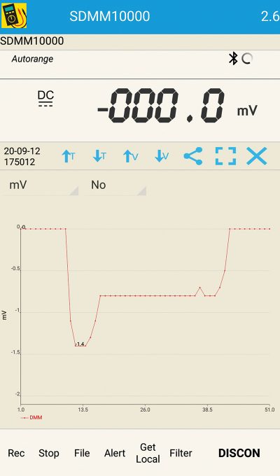
At the end of this 51 second test, the Honda is in sleep mode.
When complete, reattach the original B- cable, remove the test cable and reinstall the stainless (0.5 cm length) screw with an anti-corrosion spray.
This particular test was added to indicate when the HDS was incorrectly disconnected and the “K” line still active. This anomaly was corrected with one key/engine start cycle and returned to Off.
Keep it simple II
A charging system test should always include an AC ripple test. Just because the charging system works, doesn’t mean the alternator is producing “clean amperage.”
Garbage out, garbage in
Voltage spikes exiting the alternator also send those same spikes throughout the B+ connections and attached controllers. This will include the “K” line. In other words, use a carbon pile and make the system work either in cold or hot conditions. Test the alternator within its limits including the carbon pile (short bursts) and repeat the test with an amp clamp attached to the multimeter and with an oscilloscope operating.
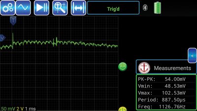
The oscilloscope waveform may express excessive AC spiking at the alternator. Constant AC voltage spikes of over one volt may be the root cause of adaptation problems and corrupt data transfer. A decent scope setting can be between 30 mA and 50 mA (per division) at one ms timebase.
Connect your lab scope as per these instructions:
- Scope red lead to B+ of the alternator.
- Scope black lead to the negative of the battery or alternator frame.
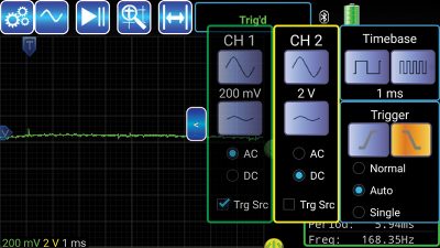
- AC spikes of up to 800 mV are somewhat safe, but overall AC ripple should be within 50 mV and 100 mV (peak to peak).
The capture at 200 mV (above) and at one ms timebase offered another view if AC ripple spikes were evident.
This particular test passed and provided confidence that the alternator would function correctly.
With the HDS and similar equipment, the diagnosis of a possible EGR related fault was a success knowing how the EGR system worked. Included is what the Engine Management System (EMS) was “looking for” when the EGR system was operating. HDS offered an on-board guided test for a pass or fail.
The parasitic draw test was a curiosity with this Accord, compared to modern Honda models. With the DLC breakout box and a schematic, this model Honda uses the “K” line to communicate within controller systems. CAN is used to send messages between the PCM, Instruments and Navigation if installed. This test measured the “time to sleep” and possible current draw when at rest.
The AC ripple test is also a curiosity because it is a test that is generally missed when testing the modern charging systems. On occasion and not often, there are instances when abnormally high AC ripple from the generator will cause unwanted or unusual controller adaptations.


The debris could be loose pieces of catalyst substrate, I have a nearly identical picture of a Ford Ranger EGR jammed open and a deteriorating converter was the culprit.