
How networks work, diagnosis and troubleshooting tips
Let’s face it: Any technician, whether dealer or independent, faces challenges in accurately and efficiently addressing communication Diagnostic Trouble Codes (DTCs), especially when multiple networks on the vehicle have multiple control modules setting communication faults.
Becoming successful and efficient at diagnosing CAN and other network protocols requires us to walk down the study path of different electrical concepts, such as inductance, impedance, phase angle, balanced antennas and more.
Although the majority of CAN faults can be found with a multimeter (See the article in the June 2017 issue of StarTuned), sometimes the faults are not so simple. Here we will discuss some ideas for those more-difficult faults.
The backbone of the communication network is its Physical and Transport Layers wired together, so all of the above listed electronic principles and more are incorporated in its construction and proper, stable operation. This is where we as technicians do our testing. The CAN node (in the module) is engineered with standardized electrical characteristics, so if we can understand what the node is doing in the system and what to expect from it, we can then read the waveform and actually get something out of it that has diagnostic chops.
The issue now becomes how do we approach these network issues, without the knowledge of packet configuration, data content, intended address, data transfer, error reporting, module acknowledgement and other key information needed to track down the faulting module or circuit? We use the tools we have available to us and figure it out on our own, that’s how.
The fault code scanner can’t help much in many of these situations anyway. Not even XENTRY Diagnostics because often, along with communications faults, sections of modules and even dare I say entire networks become completely invisible to the scanner. However, one valid technique is to look for a module that isn’t reporting any faults, or maybe doesn’t even show up in the quick test. It may be that the module doesn’t know it has gone crazy.
Moving on, some general thoughts come to mind as to why network and bus line diagnostics can become one of the toughest and most expensive problems to solve on any vehicle platform: there are so many variables and possibilities for faults to occur, and robust as the system is in design and application, it is impossible to cover them all here in this space.
And it is an extremely robust system. The CAN bus was designed to be highly fault tolerant, and man, is it ever (see Figure 1). Let’s look at some common causes of CAN faults, investigate how the system works and see if we can use this in targeting the problem at hand.
CAN Radio… Digital Radio, Broadcasting Live in YOUR Vehicle Platform
First, let’s discuss the physical layer, the wiring, connectors, termination resistors, voltages and other physical things, what we might call the CAN’s antenna. The network wires are terminated at 120 Ohms on each end of the bus (remember that two 120 Ohm resistors in parallel will measure at 60 Ohms). This is our balanced antenna for the CAN node to transmit and receive on. All other nodes are “stubbed” onto the bus in parallel, and supply signal voltage to the network.
Radio antennas are typically terminated for the purpose of “loading” the antenna to match it to the impedance of the transceiver or transmission line. CAN radios are no different: CAN nodes are impedance matched to the wire characteristics so that there is minimal signal reflection, this keeps data clean and collision free.
The CAN Bus operates with relatively high-speed data. The termination resistors are used to reduce or prevent reflections of these data signals which, if left unterminated, would cause the data and reflection voltages to overlap and prevent the bus from functioning. It is important to have a properly terminated bus to avoid these reflections.
We can compare a CAN node chip to a radio: Both are called transcievers (transmitter-receiver), both work best when terminated in their characteristic impedance, and high-frequency signals are used. As technicians, if we can start looking at CAN and data networks as radio systems, we can approach our diagnostics from a more targeted level and with a deeper understanding of how to successfully identify and solve network faults.
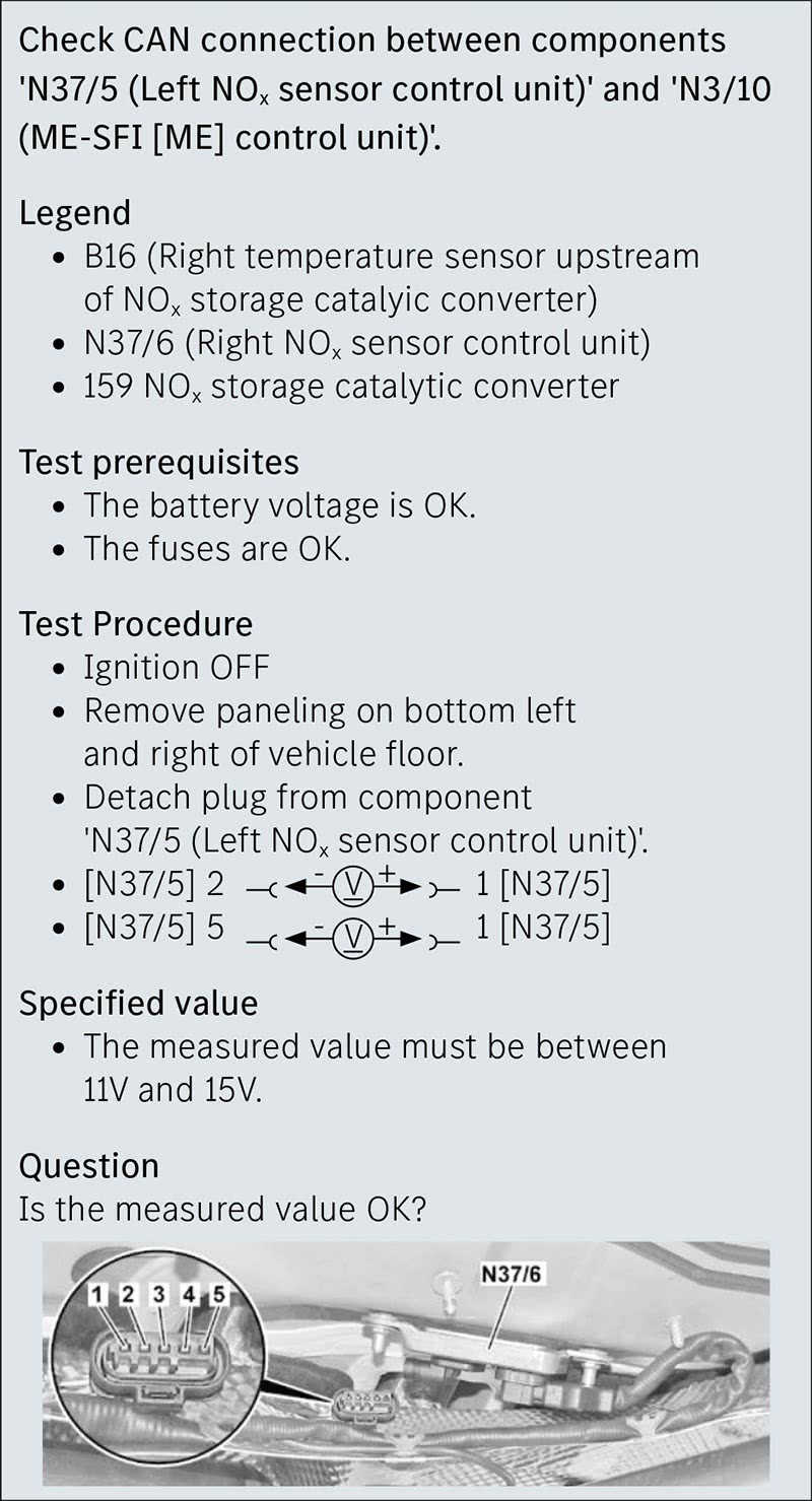
In Figures 2A and 2B (next page) a typical test plan is shown, which verifies that power and ground are being supplied to the control unit connector. After this is verified, we are then directed to test across the connector for about 60 Ohms at the connector’s CAN pins. This test sequence verifies the presence of voltage to the node, verifies the termination of the bus is OK, and assumes confirmation of no shorts or opens in the impedance balanced antenna (CAN bus wiring).
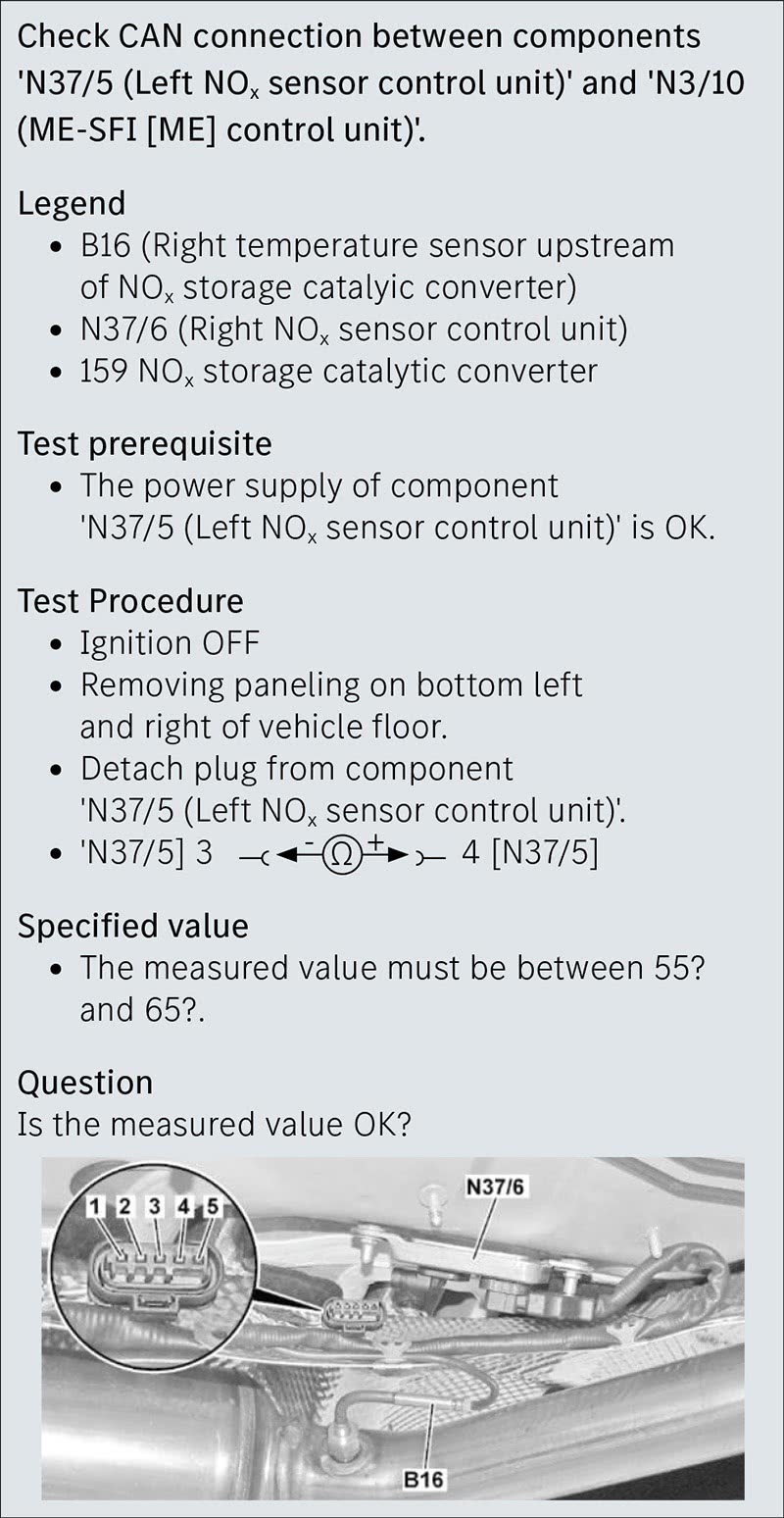
OK, so we’ve measured 60 Ohms. Since the specification is 55 to 65 Ohms, just move on, right? No problem found? Wrong.
This may be a good and valid test to check the bus termination resistors, but this is only a static test with the physical layer connector disconnected for unloaded and unpowered measurement. This is where many diagnosticians simply miss, or “cannot duplicate” the fault. Measuring 60 Ohms on an unpowered network line does not necessarily mean everything is OK.
Experience has taught us that getting the fault to happen during static bay testing rarely occurs, unless there is a module that is measurably failed, a termination resistor or wire open circuit or a bus line high-resistance issue through a connector. But these types of easier-to-find hard faults are rarely what we deal with on the street.
Now that the transceiver—antenna relationship is established, let’s hook up the scope and look at some of the waveform voltage characteristics that may help us to catch the offender…
The Three Biggies Commonly Missed—All Have to Do with Voltage
One of the most commonly overlooked possibilities for the cause of multiple communication DTCs is power supply problems. I’m talking vehicle power supply, the main and auxiliary batteries, not the CAN network power supply. One supplies the other! When we approach multi-module communication fault strings on the support line, we have learned to start with a DTC code analysis that includes any voltage-related codes outside the network and pay particular attention to solving those first.
Another frequent thing we ask the tech to do right away is to perform a starting and charging test, as we’ve found that many CAN faults—especially cascading faults—can and will set if the battery voltage falls below 9.6V, even for a fraction of a second. We catch a ton of these multi-module code strings with these first two steps. It usually happens when cranking the engine, by the way.
Beyond that basic diagnostic entry, we now need to gather an organized approach to the physical testing of the live data bus and determine what type of problem our data bus is having. All DTC charts and test plans aside, our reality out here on the street is that just like in war, the “Best-laid test plans” so to speak, can change after the first diagnostic shot is fired.
In fact, one could argue that many communications-related remote support calls we field daily are generated because the test plans provided, great as they are to use as a guide, are not sufficient in solving every issue, nor in sufficiently directing the technician in further targeted diagnosis, especially in the case of intermittent faults, which are varied and many in the communications world.
Node Faulting—Voltage Control Within the Node
These are the most common and the ugliest to catch, as a technician. Due to their intermittent nature, these faults will dog a customer, tech and shop owner, because these are usually heat or movement induced faults (mostly heat) and therefore these faults will almost never be duplicated or caught using conventional static diagnostic methodology, as shown in Figure 3.
Physical Layer (Node) Voltage Supply Problems
The third most common fault? A circuit 15 (key-on power) or circuit 30 (hot at all times) power source missing in one of the module’s circuits which, don’t forget, can be related to the energy management system’s relay control and those battery basic checks mentioned earlier.
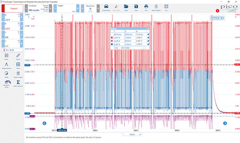
But to be direct, more often than not what we find is there is a fuse is out somewhere, and the tech “out-teched” himself because of all of the codes set. This type of fault will throw even the sharpest tech a curve ball. Figure 5 shows the DTC chart for an ME Circuit 15 Off Plausibility fault.
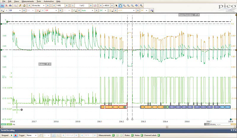
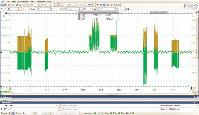
These insidious ignition-on power inputs can come from relays, other modules, even wake up signals from entirely different networks… and are one of the leading causes of needless module replacement, aka misdiagnosis. One single module unpowered in the network can set strings of DTCs and affect the bias, and eventually the signaling on the bus line. There is an explainable physical reason for this, and an example in Figure 6. If we learn to read and correctly interpret this characteristic in the waveform, we can avoid all manner of needless testing, as multiple steps are covered with one view of the live network.
If we analyze the waveform, we can clearly see that the bias voltage we expect to see at 2.5V on the high and low bus are both pulled down to 1.2V together, yet the powered-up modules are still transmitting good, acknowledged data packets. This is observed because the CAN system is a common mode voltage system where all modules put out the same voltages on the bus, and the bias (idle) voltage is produced by a voltage divider off of a regulated 5V supply rail in the module.
When all the nodes are powered and working properly, the bus operates at the 2.5V bias, and CAN high drives the signal up one volt (3.5 volts) and CAN low pulls voltage down one volt to signal at 1.5 volts, the total differential SIGNAL being 2.0 volts, one volt high and one volt low. Look carefully at Figure 6 again and notice the bias being pulled down to that 1.2V region. Why is this happening, and how can the bus still work in this condition?
Consider the voltage divider in the node that supplies the bias voltage. The 2.5 volts is provided as long as the node is properly powered up. But what if it isn’t, like in Figure 6? The node is still directly connected to the common mode system through the twisted pair, AND the termination resistor in the module. But now the common mode voltage from the awake part of the network is dropping through the unpowered node’s voltage divider, but at or near 0V ground potential. This affects the bias only, and of course, any unpowered node on the network.
When an unpowered node, or multiple unpowered nodes are on the bus, weird stuff happens.
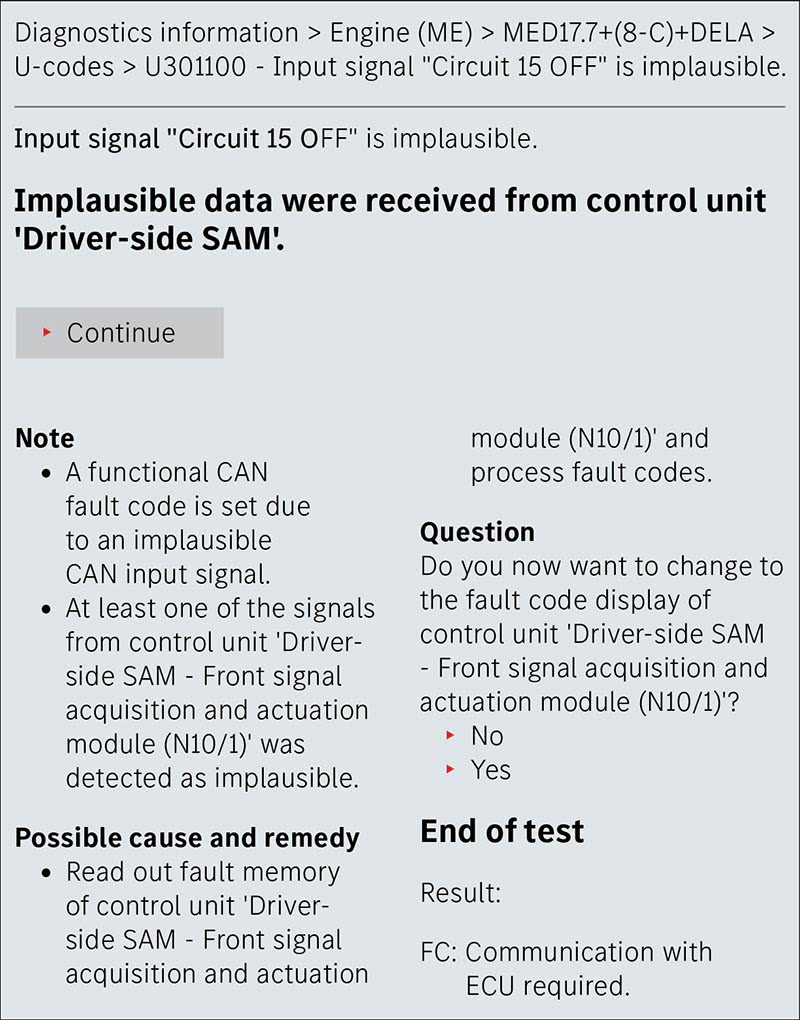
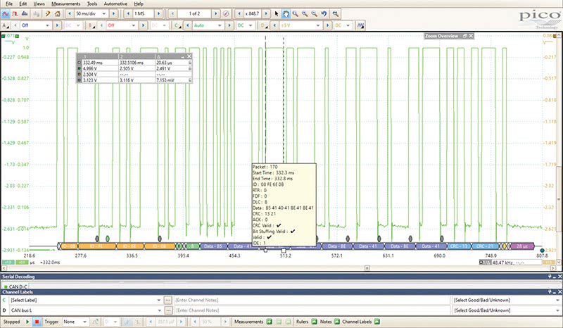
Looking at this mathematically, we can explain and prove that this waveform characteristic can only be caused by an unpowered node. The proof is that channel A+B (CAN high and low) still totals 5 volts, showing healthy common mode voltage being supplied to the impedance balanced bus by the powered nodes. Differential signal voltage being transmitted is still a total of 2 volts, one high and one low. Also, the serial decoder proves that the nodes that are still on the bus transmitting are not failing packets.
When you encounter this characteristic, we recommend you stop the CAN diagnosis and go find the missing power, wherever it originates, correct this and confirm proper bus operation prior to any module replacement. The unpowered node will get you every time if you’re not looking for the signs.
Serial Decoding
We frequently invoke the serial decoder to target faulting modules and data packets, then isolate them from the network in minutes by setting up the decoder software to take us directly to the faulting data transmission.
Since we technicians really are only able to work in the analog realm, meaning we are not in the business of repairing electronics or module repair, our main focus as techs must be on the physical testing of network data bus lines. The serial decoder function on our scope helps us find the problem quickly, when conventional testing and isolation techniques fail.
Specifically, since the published diagnostic pathway often vaporizes into computer code that we are not taught to analyze, we must depend on the physical characteristics of network waveforms to tell us what is really wrong. This means some extra study if one is to become more effective at network diagnostics.
Another important characteristic of the waveform signatures that we key in on to isolate the fault is identifying a module that is Hogging the Bus. This requires capturing and analyzing the faulting packet itself for errors.
“Hogging” the Network Bus
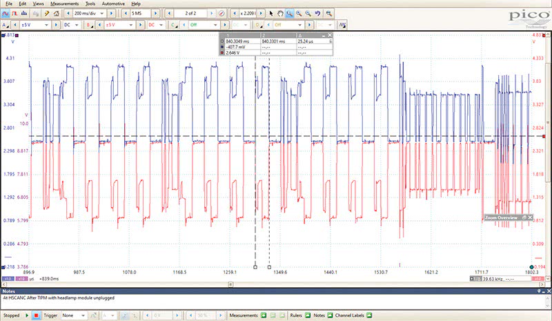
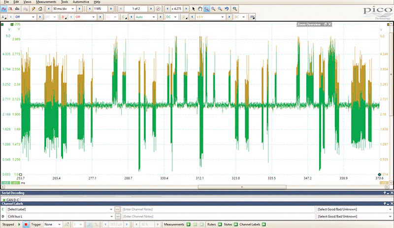
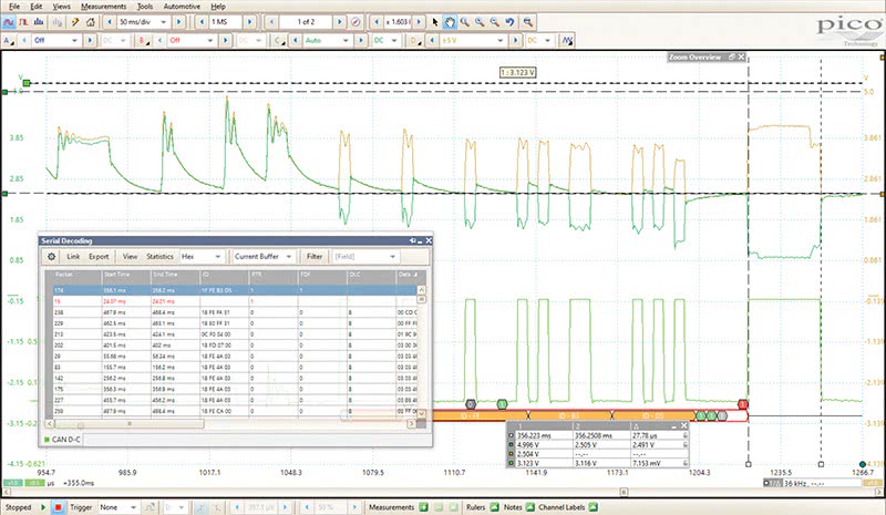
When a module is having a problem processing, transmitting, or receiving this data message, a bit count over 10us fails the packet, and the module tries to re-broadcast its message. Depending on vehicle and the problem in the node, the node will try to rebroadcast the message a preprogrammed number of times and then the node, in theory, should remove itself from the bus. But often, the node will hang, as seen in Figure 9.
In these cases, where this type of waveform is observed, you will need to isolate the suspected modules until the damaged node is removed from the bus. When the damaged node is electrically removed (disconnected) from the bus the waveform will return to normal, and you have found your offending node.
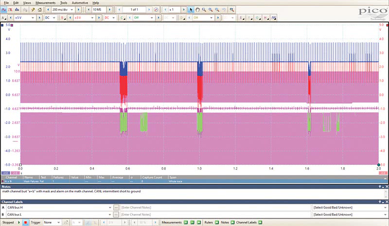
Finally, another node failure characteristic is shown in Figure 10. Note here that communications are being shorted intermittently. These are tough to find, so we typically apply masks (in pink) and alarms (in green) to our scope setup to catch these glitches, without having to search through hundreds of thousands of tiny data packets to locate our fault after we have recorded it.
Across time, many modules have been replaced needlessly due to all of the above factors plus the pressure to get the car fixed, information gaps, complexity of the networks and software, out-tech-ing ourselves along the way and probably a few other factors. But in the final analysis, on our hotline calls, we almost overwhelmingly find something simple was causing the fault the whole time. Don’t clear those codes until you capture your clues, and then use your scope for live, physical testing.
If we focus on what we can see and quantify from the analog side of the bus and then focus on learning to analyze the physical properties of our waveforms, a lot of the “communications conundrums” we face can be accurately targeted and solved with a whole lot less fuss.


0 Comments