


The design and function of this transmission, what goes wrong, and how to diagnose problems.
The Volvo TF-80SC transmission was used starting in 2005 in the V8 XC90 all the way through 2016 in most cars that had a 5-cylinder and all that had 6- and 8-cylinder engines.
The TF-80SC automatic transmission is a six-speed transmission made up of a five-pinion planetary gearset. The shifting of the gears is managed by a computer program that oversees a clutch-to-clutch actuation. These transmissions, both the TF-80SC and the TF-80SC AWD, function as two transmissions—one automatic and one manually shifting. This Geartronic transmission in automatic mode is more relaxing and the manual shifting is more for active driving.
To use the manually shifting experience, you have to push forward on the shifter to upshift to higher gears. All the forward gears in this transmission have a lockup function except first gear. The torque converter has both a locked and slipping lockup function.
The shifts are controlled by a hydraulic operating system and are completely automatic in terms of load and speed. The TF-80SC has two planetary train units, a front and a rear, and shifts are controlled by a number of clutches and brakes.
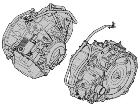
The shape of the transmission casing is dependent on which engine the vehicle has.
The transmission has eight solenoids that control the hydraulic flow; six of the solenoids control the shift process. One solenoid controls the torque converter lockup and one solenoid controls the system pressure throughout the transmission.
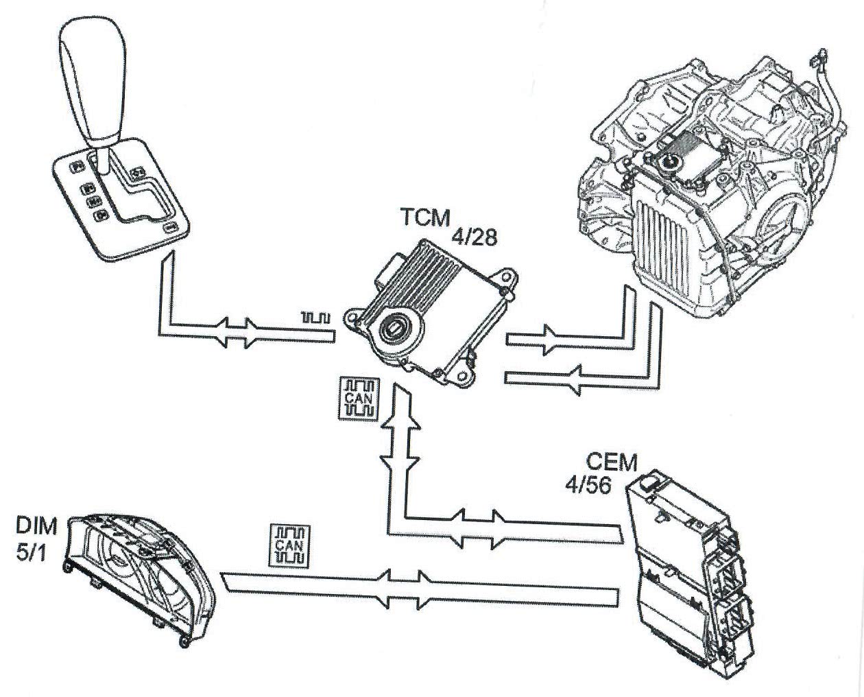
The Transmission Control Module (TCM) is located on the transmission itself. The advantage of this is the elimination of external wires. Gear changing happens when one clutch engages the instant the previous gear disengages.
Design and Function of the TF-80SC AWD Transmission
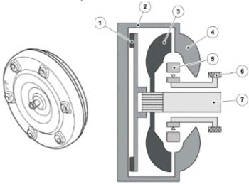
The torque converter consists of three impellers. The first impeller is connected to the crankshaft. The pump rotor is inside the metal housing and rotates with the crankshaft.
The second impeller, the turbine rotor, is connected to the transmission’s input shaft and is driven by the oil that is circulated by the pump rotor. The stator, which is the third impeller, is between the pump rotor and the turbine rotor.
The torque converter is like a hydraulic automatic clutch. Remember your old go cart? It would sit still until you gave it gas, then it would take off. The torque converter works the same way. At idle, the pump action is too weak and then, as speed increases, the turbine rotor inside the torque converter starts to engage and drives smoothly.
With slow speed driving, the impellers inside the torque converter slip a little bit. That affords a power loss, and this increases fuel consumption. When the vehicle is moving, the torque converter’s reinforcement of the engine’s torque is not needed. This is when the lockup function is activated and the transmission input shaft is connected with the engine mechanically. Fuel consumption is reduced when the engine speed drops and the torque converter’s slipping disappears.
The planetary gear system consists of a conventional planetary gear connected to a Ravigneaux planetary gear. The Ravigneaux planetary gear setup is unique to this TF-80SC transmission. There are three clutches and two brakes that control the gear ratios in this transmission.
| No. | Designation | No. | Designation |
|---|---|---|---|
| 1 | Rear planetary train (Ravigneaux) | 6 | Input shaft |
| 2 | Front planetary train | 7 | Drive gear |
| 3 | Planetary gear | 8 | Oil pump |
| 4 | Sun gear | 9 | Differential |
| 5 | Ring gear | 10 | Driven counter-rotaing gear |
The oil pump for the transmission is located at front of transmission and is accessible when the torque converter is removed; it’s driven from the crankshaft via the torque converter. The pump supplies the transmission with oil to lubricate and cool the transmission. There is an external oil cooler to help cool the transmission as well.
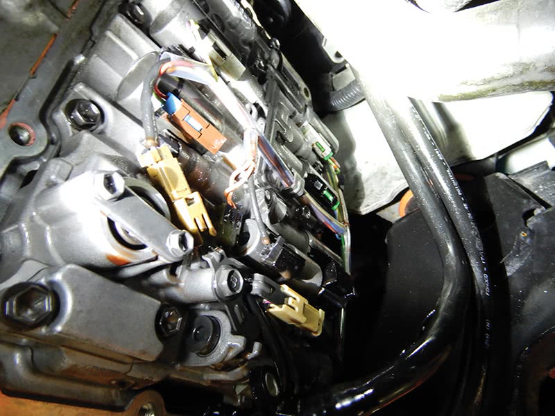
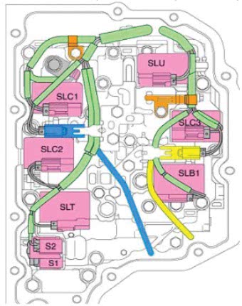
Inside the transmission pan is the valve body. The valve body contains solenoids and hydraulic valves. The solenoids are activated by the Transmission Control Module (TCM). Hydraulic pressure builds up inside the transmission, and the hydraulic valves, which are controlled by their solenoids, send hydraulic pressure to the relevant clutch.
As the clutch rotation speed increases, the centrifugal force affects the oil inside the clutch, and the pressure increases and the clutch engages.
In the all-wheel drive vehicles, the TF-80SC transmissions look a little different, but inside are primarily the same. All-wheel drive vehicles have a transfer case that is mounted on the transmission that connects the driveshaft to the rear differential; that transfers the power to the rear wheels.
The product plate on top of the transmission serial number will identify the production year, month, and transmission model. The first two numbers in the serial number are the year (07 indicates 2007). The third number indicates the production month (A would be January and so forth). The four and fifth numbers indicate the transmission, in this case, TF-80SC.

The gear selector assembly inside the vehicle has a cable that runs to the transmission to select which gear you want the transmission to be in. Park, Reverse, Neutral, Drive, and Manual shifting. The manual shifting position is controlled by pushing the shifter up or down to change gears manually.
Using the correct transmission fluid is important in these transmissions. The electronic controlled transmission system has a transmission control module with software that uses input information from the transmission sensors and other control systems to make decisions on gear selection, torque converter lockup, and gear shifting timing.
The transmission valve body gets commands from the transmission control module to activate solenoids in the valve body to control shifting, torque converter lockup, and line pressure in the transmission.
Volvo says the transmission fluid is a lifetime fill unless the car is used as a taxi or for towing, in which case it gets changed at 52,500 miles or 50,000 miles depending on the vehicle’s service program. On high mileage cars, changing the fluid may provide improved shift feel.
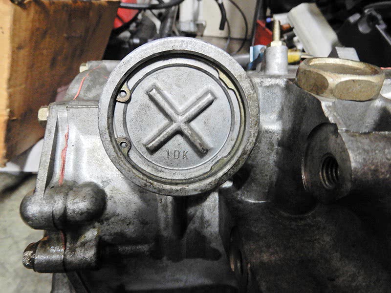
After the transmission is drained, with a new washer, install the first plug with the long tube, the level indicating pipe. Adding fluid can be done at the bottom of this plug by injecting transmission fluid into the plug until fluid starts to escape. Insert the smaller plug and start the vehicle up and monitor it on VIDA; go to Vehicle Communication > TCM Transmission Control Module > Monitor Temperature Of Fluid. The fluid should be between 50 and 60 degrees C and just dripping out in small drops.

Fluid can also be added at the top of the transmission. Remove the air filter housing to expose the fill plug. Doing it this way, you will need to add three to four liters. Set the filter housing back in place, start the vehicle and check at the bottom plug. (See “transmission fill plug” image on next page.)
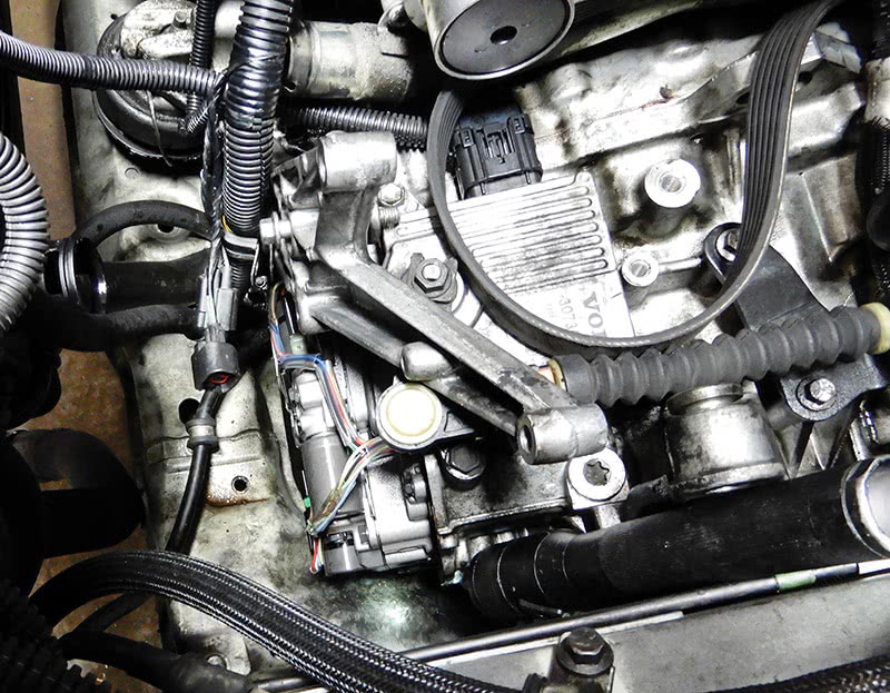
Transmission oil leaks can be spotted pretty easily most of the time. The most common are at the pan that covers the valve body controls, the B1 servo. The other common leak is actually motor oil from the rear main seal between the engine and transmission.
The complete transmission will have to come out to replace this seal. The B1 servo cover can be replaced and is now available separately from Volvo. There are two kits for repairing this job, for low torque and high torque engines. The low torque engine is XC70 (08-) engine B6324S, and the high torque version is found in other engines. The low torque part number is 31259740 and high torque 31259757; you will also need transmission oil. Use fluid part number 1161540 and 1161640 for the generation 1 TF80. Later transmissions take 31256775 or 31256774 depending on bottle size.
Replacing this B1 servo depends on the model and year to access the servo. Volvo now has a replacement kit for sealing the servo.
Here are the affected vehicles:
- S80 2007- All chassis range
- V70 2008- All chassis range
- XC70 2008- All chassis range
- XC60 2010- All chassis range
- XC90 2005- All chassis range
- V70R 2006-2007 All chassis range
- S60R 2006-2007 All chassis range
Drain the transmission fluid. Clean the area around the servo so not to contaminate inside the transmission. Remove the lock ring and remove the servo piston. If the piston is damaged, the transmission will need to be replaced.
Clean the components and make sure there are no burrs on the piston ring groove. If there are burrs, use a fine emery cloth to remove them. Install the piston with new O-rings into the transmission and push down and install the lock ring.
Fill the transmission with new fluid per VIDA and check to make sure the transmission is filled correctly.
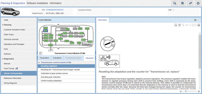
Connect VIDA to the vehicle; go to Vehicle Communications > TCM Transmission Control Module. Click on the Advanced tab > Control Module Adaption and reset the adaption.
You can find this information in the Technical Journal 21096 AW TF-80SC Servo Cover, automatic fluid leak.
Making sure the transmission and engine control modules have the latest software is very important. This doesn’t mean that software will cure a customer’s problem in their transmission simply by upgrading the software.
Technical Journal 16761 talks about rough shifting, harsh engagement or shift shock after standing still after brake pedal release. We will go over this Technical Journal and talk a little about it and the symptoms of the vehicle. (Log into volvotechinfo.com/account/library/library to look up TJ 16761 for more information.)
| Code | Description |
|---|---|
| AE | Idling/Uneven idle |
| DL | Warning lights and chimes/Malfunction Indicator Light (“Check engine” light) indication/no indication |
| EX | Warning lights and chimes/Automatic transmission indication/no indication |
| 7Y | Automatic transmission/Gear changes take too long to complete/Unsure when/at all times |
| 7Z | Automatic transmission/Shifts occur too early, too late, too often/Unsure when/at all times |
| MA | Automatic transmission/Shifts rough or jerky/Unsure when/at all times |
| MC | Automatic transmission/Winter mode does not work |
| MD | Automatic transmission/No automatic gearshift |
| ME | Automatic transmission/Shifts occur too early, too late, too often/When upshifting |
| MH | Automatic transmission/Kickdown does not work |
| MO | Automatic transmission/Shifts occur too early, too late, too often/When downshifting |
| MV | Automatic transmission/Gear changes take too long to complete/When downshifting |
| NB | Automatic transmission/Gear changes take too long to complete/When upshifting |
| ND | Automatic transmission/Shifts rough or jerky/When downshifting |
| NF | Automatic transmission/Shifts rough or jerky/When engaging gear at standstill |
| NO | Automatic transmission/Shifts occur too early, too late, too often/From Park to Reverse or Drive |
| NS | Automatic transmission/Shifts rough or jerky/When upshifting |
| OC | Manual transmission/Gear pops out |
| NY | Automatic transmission/Vibration |
| Control Module | Code | Fault Type |
|---|---|---|
| TCM | P089500 | Intermittent |
| TCM | 012B | Intermittent |
| TCM | 012A | Intermittent |
| TCM | 002F | Intermittent |
| TCM | 0045 | Intermittent |
| TCM | 0053 | Intermittent |
| TCM | 008D | Intermittent |
| TCM | 0028 | Intermittent |
| TCM | 0099 | Intermittent |
| TCM | 002E | Intermittent |
| TCM | 530D | Intermittent |
| TCM | p074400 | Intermittent |
| TCM | p073000 | Intermittent |
| TCM | 002A | Intermittent |
| TCM | 002B | Intermittent |
| TCM | 0029 | Intermittent |
Removing Transmission Oil Pan to Reseal or Remove Valve Body and/or Replace Solenoids
First thing to do is to remove the air filter housing. Depending on the year and model, the ECM could sit on top of the air filter housing and will need to be removed. If the ECM needs to be removed, disconnect the negative battery terminal first.
Disconnect the air mass sensor and remove the air hose from the air filter housing and at the throttle module and set aside.
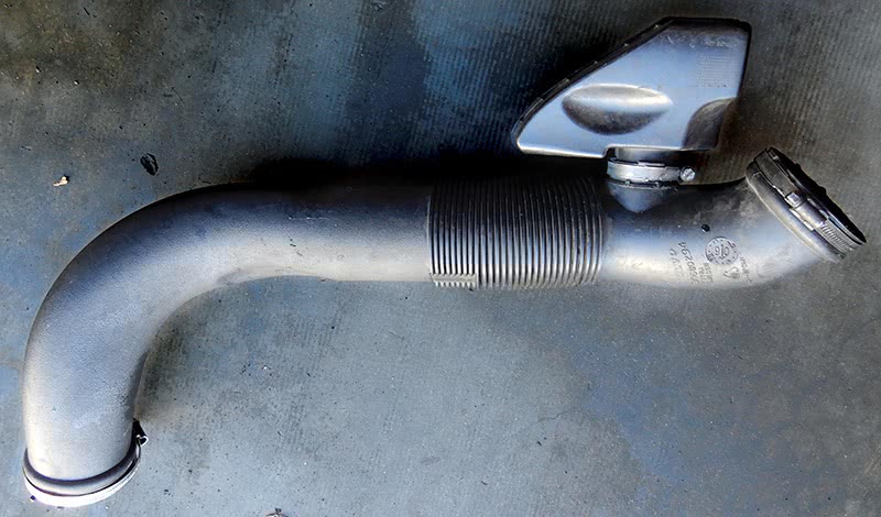
Pull up on the filter housing and remove it from the vehicle. Remove the battery from the vehicle and battery box; four bolts hold the box in place. The air conditioning compressor will need to be removed on XC90 SI6 models; on other models, you can simply move the compressor to the side. On these XC90 models, you will have to remove the refrigerant from the A/C system using a machine suitable for R134.
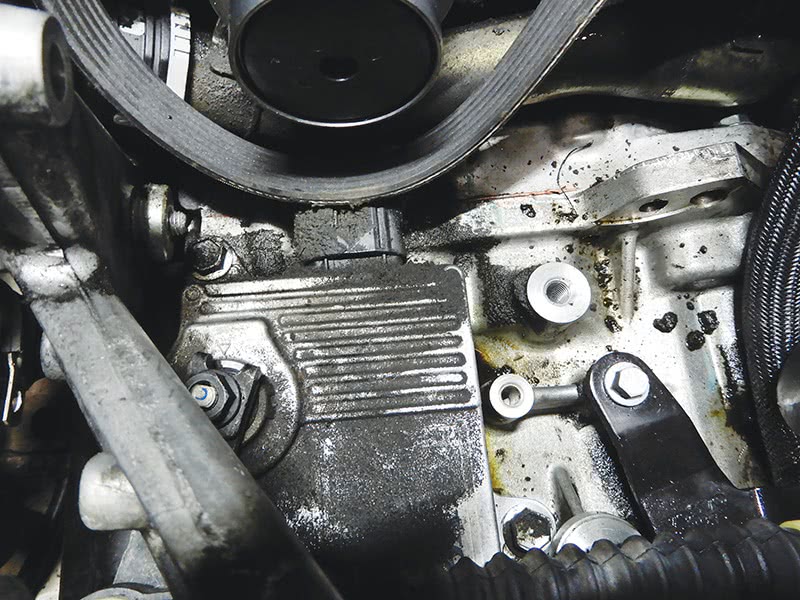
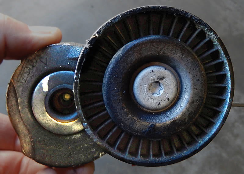
Once the refrigerant is removed, disconnect both A/C lines from the compressor and tuck them out of the way. Remove the power steering hose bracket that sits on top of the A/C compressor if equipped. Using a 19 mm wrench, release the pressure at the drive belt tensioner and insert a 3 mm pin to lock the tensioner in place so the belt is loose. (See image next page.)
Now remove the other bracket from engine to A/C compressor and set it aside. There is also a bracket at the A/C compressor to the top of the transmission that needs to come off.
Disconnect the two electrical connectors at the A/C compressor and remove the bolts that hold the compressor into place. Lift off the compressor and put tape over the two hose lines so not to let debris and moisture into the compressor.
Remove the bolt that holds the belt tensioner to the bracket and remove the belt tensioner. Remove the bracket that holds the A/C compressor in place and set aside.
Drain coolant from vehicle and disconnect the bottom radiator hose that is in front of the transmission pan. Raise the vehicle in the air and drain the transmission fluid. Remove the lines at the transmission that are in front of the pan and tuck them out of the way.
Now remove the 12 bolts that hold the pan in place and remove the pan from the transmission. Depending on what you’re doing, resealing the pan or replacing solenoids or even replacing the valve body may be necessary. On certain vehicles it might be necessary to lower the subframe to remove the pan.
After repair and replacing parts, make sure to clean the surface and the oil pan. If you’re replacing solenoids, make sure that any electrical connectors are secured and clipped into place so they don’t disconnect.
Add a bead of chemical gasket, part number 31316436, 3 mm thick, around the pan and set it into place. Install the 12 bolts holding the pan in place and torque to 13 Nm.
Now you can start reinstalling all parts starting with the lines that go to the transmission. Install new O-rings so there are no leaks.
Install the bracket that holds the A/C compressor in place and secure. Connect the radiator hose. Install the drive belt tensioner and route the drive belt in the correct way. Set the A/C compressor in place and bolt down and connect the electrical connectors.
Once the A/C compressor is in place remove 3 mm pin using a 19 mm wrench to release the pressure. Install the A/C low and high pressure lines with new O-rings and tighten. Add the brackets at the compressor and the power steering hose and bracket if so equipped.
Install the battery box and battery but don’t connect the terminals yet.
Install the plastic hose from the throttle housing, install the air filter housing in place and connect the hose from the throttle body and tighten. Connect the air mass meter. Set the power steering reservoir in place and connect the hoses. If needed, set the ECM in place on the air filter housing and connect.
Connect your A/C machine and install refrigerant to the proper value. Fill the transmission with fluid and add coolant to the engine. Connect the battery terminals and start the engine. Connect VIDA to the vehicle; go to Vehicle Communication > TCM > Check Temperature Of Transmission until the engine is warmed up and check fluid level until fluid just drips out. Secure the plug. If you replaced the valve body or solenoids, you will need to reset adaptions in VIDA. Test drive to make sure all is well. Recheck the fluid level and all repairs.


0 Comments